
Card Edge Connector Engineering
PCIe Connector Types: What Buyers Need to Verify
What are the different types of PCIe connectors? For sourcing, separate the answer into two groups: motherboard card-edge slots identified as x1, x4, x8, and x16, and auxiliary power connectors used by some add-in cards. A part should not be approved from its visible size alone. Lane routing, card geometry, the mating power assembly, and the system drawing all need to agree.
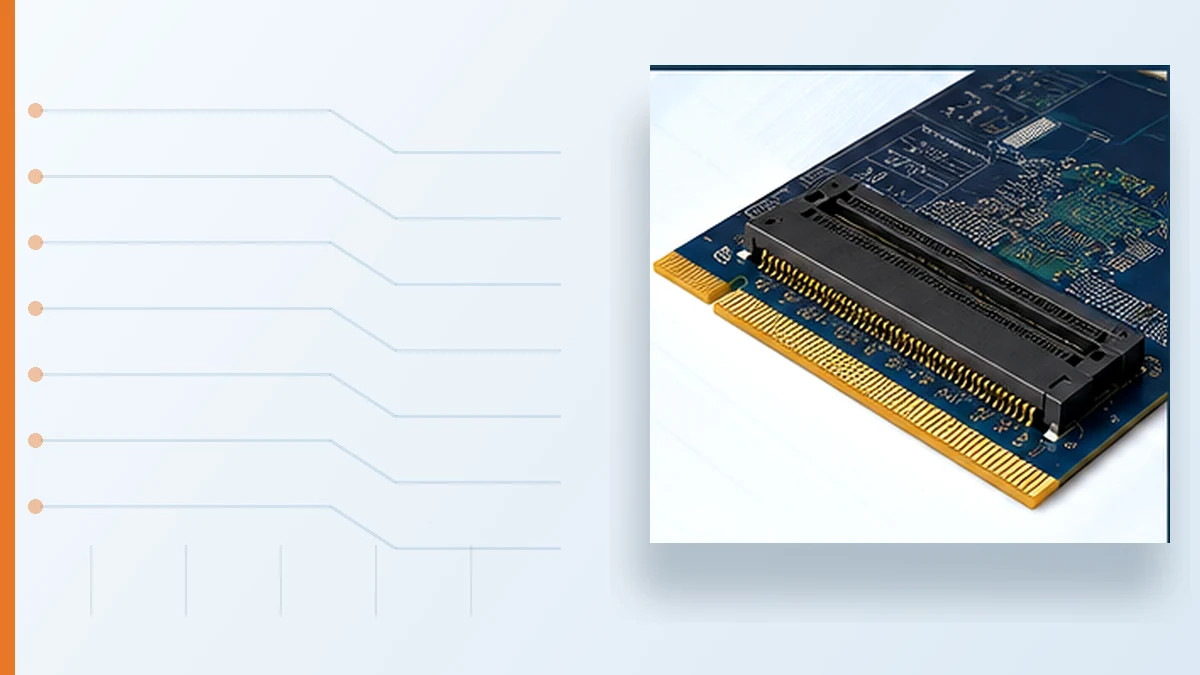
First Separate the Slot Connector from Auxiliary Power
The PCIe slot is the card-edge interface on the motherboard. Auxiliary power is a separate cable-side connection used when the add-in card design calls for it. Mixing these two decisions creates incomplete RFQs: the slot may be correct while the cable assembly, keying, or detection contacts remain undefined.
Engineering check: ask for the add-in card documentation and motherboard drawing before selecting either interface. A catalog photo does not confirm routed lanes, power requirements, or cable compatibility.
PCIe Slot Types: x1, x4, x8, and x16
The slot name indicates the supported lane width. The connector generally becomes longer as lane count increases, but the mechanical opening does not prove how many lanes the motherboard actually routes. Procurement should record both the physical slot and the electrical lane configuration.
| Slot type | Lane width | Buyer review point | Risk if omitted |
|---|---|---|---|
| x1 | 1 lane | Confirm card clearance, routed lane count, and PCB edge geometry. | A mechanically suitable slot may still fail the endpoint requirement. |
| x4 | 4 lanes | Check routed lanes, connector retention, and edge-finger drawing. | A footprint decision can be made before the system architecture is frozen. |
| x8 | 8 lanes | Review chassis clearance, insertion access, and signal transition. | Card engagement or available bandwidth may not match the visible slot. |
| x16 | 16 lanes | Verify full card fit, actual lane routing, retention, and power documentation. | Late discovery can force PCB, chassis, or cable changes. |
A shorter card may enter a longer open-ended slot, but that does not complete the compatibility review. The motherboard, endpoint, firmware, and mechanical envelope remain system-level checks. A substitute should therefore be approved against controlled drawings, not because it appears to fit.
Auxiliary PCIe Power Connectors Need Their Own Review
Common auxiliary families include 6-pin, 8-pin, and 12VHPWR configurations. They are not interchangeable purchasing labels. The approved choice comes from the add-in card documentation and the matching power-supply cable assembly.
- Connector configuration: use the exact card-side requirement shown by the system owner.
- Cable-side keying: confirm the mating cable belongs to the selected power supply and assembly.
- Detection contacts: review any sense-contact or grounding requirement shown in the drawing.
- Routing and strain relief: check bend space, connector access, and cable retention inside the chassis.
Do not infer electrical capability from the housing shape or contact count. Loading, wire construction, protection, and the approved cable set must be validated by the system owner.
Card-Edge Geometry Controls Mating Quality
PCIe is a card-edge interface, so the connector and PCB cannot be reviewed independently. Before a supplier quotes tooling, samples, or production, compare the connector drawing with the customer PCB drawing.
- PCB thickness and tolerance
- edge-finger layout and entry bevel
- contact finish requirements stated by the drawing
- keying, polarization, and connector orientation
- mounting, retention, and chassis keep-out limits
- target mating cycles and operating environment
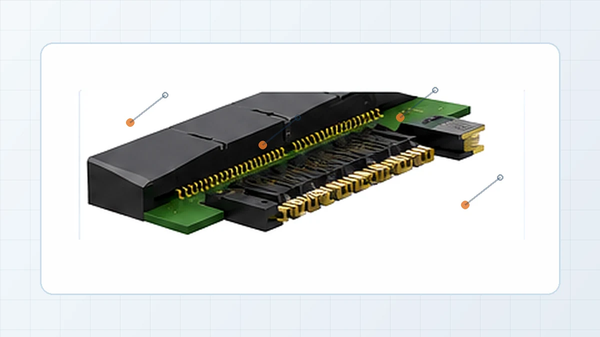
For application-specific projects, LinkManu’s card edge connector family is a starting point for reviewing pitch family, contact count, keying, mounting, and plating requirements. Availability and final construction remain subject to the customer drawing and RFQ scope.
Review Signal and Mechanical Constraints Together
High-speed performance depends on more than the socket. The connector transition, PCB stack-up, routing, motherboard design, and add-in card all contribute to the channel. Engineering should confirm the intended lane configuration and applicable interface documentation before releasing a footprint.
Mechanical checks belong in the same review. Verify insertion access, card retention, housing clearance, and tolerance stack-up. A prototype fit check can expose incomplete engagement or interference before production inventory is committed, but it does not replace the electrical validation plan.
Buyer Checklist Before Sending an RFQ
- State the required PCIe lane width and the number of lanes actually routed by the motherboard.
- Provide the target slot or mating connector drawing, not only a catalog description.
- Include PCB thickness, edge-finger layout, bevel, and finish requirements.
- Confirm whether the add-in card needs auxiliary power and identify the approved mating cable assembly.
- Record retention, vibration, mating-cycle, and environmental conditions that affect the interface.
- List the drawings, samples, and validation records required for supplier approval.
- When evaluating a second source, define which changes would trigger requalification.
Unknown items should remain open engineering questions. Turning them into purchasing assumptions is the fastest way to approve the wrong connector or cable assembly.
Common Approval Mistakes
Using physical fit as the compatibility decision
A card entering a slot only confirms part of the mechanical relationship. Routed lanes, endpoint requirements, firmware support, and the full card envelope still need review.
Treating auxiliary power as a late BOM item
The card-side connector, power-supply interface, cable construction, detection contacts, and chassis routing form one assembly. Approving them separately can leave no verified mating solution.
Accepting a substitute from a similar description
Similar names can hide differences in PCB geometry, keying, mounting, finish, or retention. Compare controlled drawings and qualification requirements before approving an alternate.
Frequently Asked Questions
What are the different types of PCIe connectors?
The main motherboard slot types are x1, x4, x8, and x16. Some add-in cards also use auxiliary power connectors such as 6-pin, 8-pin, or 12VHPWR. Review the slot and power assembly separately.
Does it matter which PCIe slot I use?
Yes. The physical slot, routed lane count, endpoint requirement, card clearance, and system documentation must match.
What should I send a connector supplier?
Send the PCB drawing, edge-finger details, mating connector or slot requirement, mounting limits, environment, mating-cycle target, and cable drawing when auxiliary power is involved.
Send Your Connector Requirement
Share the PCB drawing, BOM, target application, mating details, and open engineering questions. The review should confirm lane configuration, card-edge geometry, auxiliary power requirements, environment, documentation, and supplier capability before final selection.

Technical content reviewed by LinkManu Engineering Team
Prepared by LinkManu Editorial Team for B2B connector engineers, sourcing teams, and product development projects.