
Card Edge Connectors for PCB Edge Slot Interfaces
LinkManu card edge connectors support PCB edge-card insertion, gold-finger style interfaces, board module connection and drawing-based connector selection for industrial electronics, LED display systems, communication equipment and server-related projects.
Interface focus
Insertion style
Available for review
Project validation
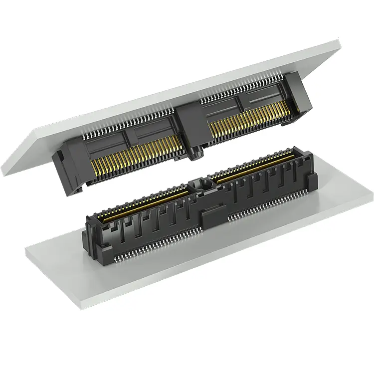
Built Around the PCB Edge Interface, Not General Board Stacking
Card edge connectors are selected when a PCB edge, module card or gold-finger contact area must plug into a connector slot. This makes the page different from a standard board-to-board connector page, which usually focuses on pitch, stack height, mating direction and board-to-board spacing.
PCB Edge Interface
Review the PCB edge contact area, board thickness, insertion direction, keying and mechanical envelope before connector selection.
Slot-Style Mating
Use edge-card slot mating when a removable board module needs a compact and repeatable connection path.
Project Review
Pitch, contact count, board thickness, plating, power path and application requirements should be confirmed with drawings or samples.
Card Edge Connector Selection Data to Confirm
The currently available source data confirms Card Edge Connectors / Slot Connectors as a product category, but detailed pitch, contact count, plating and complete datasheet information should be confirmed before publishing SKU-level claims.
| Review Item | Conservative Website Position | What to Confirm During RFQ |
|---|---|---|
| Connector type | Card edge connector, edge-card connector, PCB card edge connector and card edge slot connector. | Target interface type, mating card structure and connector orientation. |
| PCB interface | PCB edge insertion and gold-finger style board contact interface. | PCB thickness, edge chamfer, contact pad layout, keying and mating depth. |
| Pitch and contact count | Available for engineering review. Do not assume unlisted values before drawing confirmation. | Required pitch, total positions, single-side or dual-side contact layout and footprint. |
| Signal and power paths | Selected signal, power and power + signal card edge options may be reviewed project by project. | Current path, signal requirement, grounding arrangement and thermal condition. |
| PCIe / Mini PCIe style applications | Selected series may be reviewed for PCIe or Mini PCIe style card-slot projects when customer requirements are available. | Standard, pinout, mechanical drawing, data-rate expectation and validation plan. |
| Alternative review | Selected pin-compatible alternatives may be reviewed. | Existing part number, 2D drawing, sample, datasheet and application environment. |
Final connector selection should be confirmed against the customer drawing, PCB edge design, mating direction, and validation requirements.
Card Edge and Slot Connector Options
Use this page to review card edge connector options for PCB edge insertion, gold-finger interfaces, and removable board module connections.
Card Edge Slot Connectors
Slot-style connectors for PCB edge insertion and removable board module interfaces.
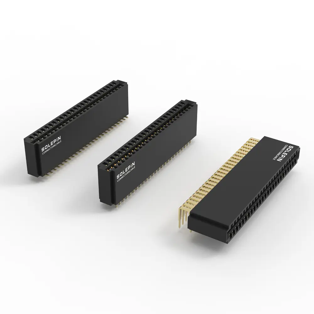
PCB Card Edge Connectors
Connector options for PCB edge-card interfaces where board thickness, footprint and mating depth must be reviewed.
Power + Signal Card Edge Review
Selected card edge connector projects may require combined power and signal contact review before sampling.
Where Card Edge Connectors Fit
Card edge connectors are suitable when the design needs a direct PCB edge interface instead of a cable assembly or a conventional mezzanine board-to-board pair. LinkManu can review card edge connector requirements for equipment-level and module-level projects.
- Server-related board modules and card interfaces.
- Industrial control boards and removable modules.
- LED display control, power and signal interface projects.
- Communication equipment and board-level assemblies.
- Power + signal card edge connector review projects.
- PCIe or Mini PCIe style slot projects when confirmed by drawings.
From Edge-Card Requirement to Manufacturable Connector Selection
Card edge connector sourcing should be handled as an engineering review, especially when the application involves compact PCB modules, power paths, signal integrity concerns or pin-compatible alternative review.
Submit Requirement
Send the target connector type, board thickness, PCB edge drawing, current connector part number, sample photos and expected annual quantity.
Interface Review
Review edge-card contact layout, mating depth, keying, contact arrangement, power path and mechanical envelope.
Sample Validation
Confirm mechanical fit, insertion feel, contact stability, board alignment and project-specific electrical requirements with samples where feasible.
Production Support
Support tooling, molding, stamping, assembly, inspection and delivery according to the confirmed drawing and project scope.
Confirm the Interface Before Volume Purchase
The correct card edge connector depends on both connector geometry and PCB edge design. For B2B sourcing, LinkManu recommends confirming drawings, samples and validation requirements before mass production.
- Check PCB thickness and edge-card contact layout.
- Confirm connector orientation, footprint and insertion direction.
- Review material, plating and packaging requirements during RFQ.
- Validate fit and function in the final equipment environment.
RFQ Information to Prepare
A clear RFQ helps reduce back-and-forth communication and prevents unsuitable connector selection.
- Part number, drawing or sample photos.
- PCB thickness, pad layout and board edge structure.
- Signal, power and grounding requirements.
- Application, quantity, sample schedule and validation plan.
Build a Complete Board-Level Interconnect Solution
Card edge connectors are often reviewed together with board-to-board connectors, high-speed connectors, floating connectors, wire-to-board connectors and cable assemblies.
Card Edge Connector FAQ
Answers for engineers and sourcing teams reviewing PCB edge-card slot connector projects.
What is a card edge connector?
A card edge connector is a slot-style connector used to mate with the edge of a printed circuit board. The PCB edge usually carries exposed contact pads or a gold-finger style interface that plugs into the connector slot.
How is a card edge connector different from a board-to-board connector?
A board-to-board connector usually mates two connector halves and is often selected by pitch, stack height and mating direction. A card edge connector focuses on the PCB edge itself, the slot interface, board thickness, contact pad layout and insertion design.
Is this page positioned as a high-speed connector page?
No. Some card edge projects may involve PCIe or other high-speed interfaces, but this page is positioned around PCB edge slot mating. High-speed performance should only be discussed after the specific series, drawing and validation data are reviewed.
Can LinkManu review PCIe or Mini PCIe style card slot requirements?
Selected series may be reviewed for PCIe or Mini PCIe style card-slot projects when the customer provides the mechanical drawing, standard requirement, pinout, PCB thickness and validation plan.
Can LinkManu review Samtec, Molex, HRS or TE alternatives?
For selected projects, selected pin-compatible alternatives may be reviewed. Final suitability must be checked with drawings, dimensions, electrical requirements, mating parts and sample validation.
What should I send for a card edge connector RFQ?
Please send the target connector type, existing part number, PCB edge drawing, board thickness, contact count, pitch, application, sample request and expected annual quantity. Photos and validation requirements are also helpful.
Need a Card Edge Connector Review?
Send your PCB edge drawing, current connector part number, sample photos or target application. LinkManu can review card edge connector options and selected pin-compatible alternatives based on project requirements.