
Product Category
Wire-to-Board Connectors for PCB-to-Wire Interfaces
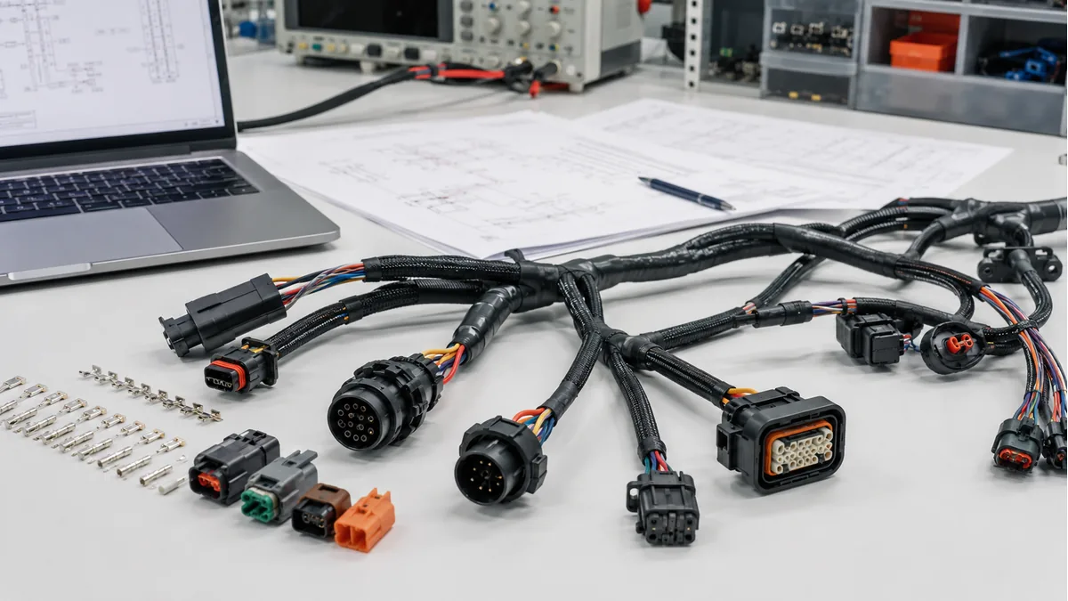
LinkManu supports wire to board connectors for internal device wiring, PCB headers, wafer housing connector projects, IDC connector assembly projects, and crimp style connector interfaces.
PCB-to-wire
For internal wiring between a PCB and a cable or harness-side connection.
0.8mm / 4P
Source-material example: 0.8mm crimp style 4P IDC connector assembly.
Wafer / header / housing
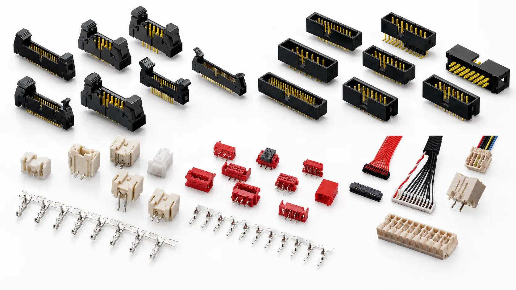
Wafer housing, ejector header, box header, and IDC-style projects may be reviewed.
Drawing review
Selected fit-style connector options may be reviewed for project requirements.
Category Overview
Board-side connector options for internal PCB-to-wire routing
Wire-to-board connectors are used where a PCB needs a reliable interface to a wire, cable, or internal harness. This page focuses on board-side connector selection, including wafer and housing interfaces, box header and ejector header styles, and IDC or crimp-style assembly examples.
For PCB-to-PCB mating, use Board-to-Board Connectors. For processed wires, harness routing, cable length, and assembly manufacturing, use Cable Assemblies.
Typical project review points
- PCB header or wafer interface
- Housing and mating direction
- Crimp or IDC assembly requirement
- Pitch and position count shown in the drawing
- Selected fit-style connector options for review
Engineering Reference
Wire-to-board connector reference table
The following items are conservative reference categories from source materials. Final suitability depends on the drawing, mating requirement, and project-specific validation.
| Reference category | Supported description | Use on this page | RFQ information to send |
|---|---|---|---|
| 0.8mm crimp style 4P IDC connector assembly | Source-material example includes 0.8mm pitch, 4-position, crimp-style / IDC assembly reference. | Example of compact PCB-to-wire assembly support. | Share the drawing, mating side, and cable-side requirement. |
| Wafer housing connector options | Source-material examples include 0.60 / 0.80 wafer housing connector, 1.27 wafer housing connector, and 1.50 wafer housing connector references. | Board-side connector family for internal wiring interfaces. | Share pitch, positions, mating housing, and project drawings. |
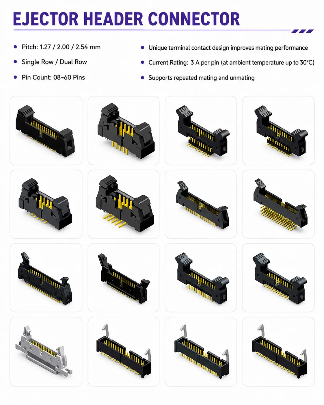
| Ejector header connector | Source materials reference ejector header connector options within the wire-to-board connector category. | For projects requiring a guided or ejector-style board header review. | Share the mechanical direction and mating cable assembly requirement. |
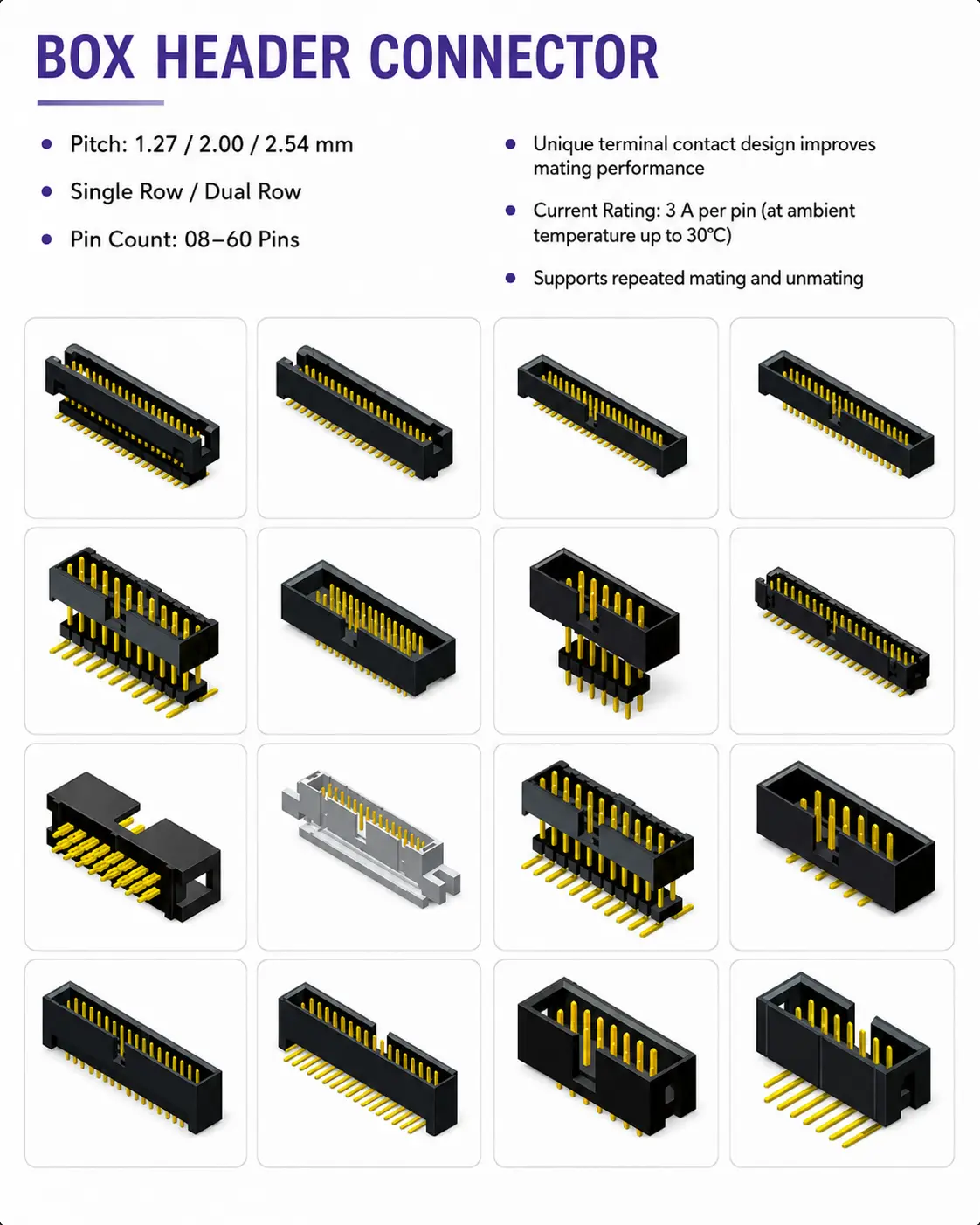
| Box header connector | Source materials reference box header connector options within the wire-to-board connector category. | For projects requiring a boxed PCB header interface. | Share pin count, keying requirement, and IDC or ribbon cable requirement. |
| Crimp and IDC interface projects | Crimp-style and IDC assembly examples may be reviewed as connector interface projects. | Connector-side review only; cable processing details should be handled with Cable Assemblies. | Share cable-side drawings and mating connector information. |
| High-current wire-to-board review | High-current wire-to-board projects may be reviewed. | Secondary coverage only; main power-focused projects should use the Power Connectors page. | Share the project drawing and required operating conditions for separate review. |
Supplier Range
Wire-to-board connector pitch and mounting matrix
Current source materials show the following connector families. A complete interface normally includes the PCB-mounted wafer or header, a mating crimp housing, terminals, and the optional finished cable assembly. Availability, position count, mating parts, and electrical ratings must be confirmed against the approved drawing before quotation.
| Pitch / family shown | Board-side forms shown | Typical project fit | Confirm for RFQ |
|---|---|---|---|
| 0.60 / 0.80mm A0601 / A0800 |
Right-angle SMT; vertical SMT shown for 0.80mm | Compact internal PCB-to-wire interfaces | Positions, mating housing, terminal, footprint |
| 1.0 / 1.2mm | Right-angle and vertical; latch and dual-row examples shown | Low-profile or compact internal wiring | Latch, row count, height, mating parts |
| 1.25mm MX / GH / K / T styles |
Right-angle, vertical, DIP 90° and DIP 180° examples | Compact signal and device wiring | Exact series, height, keying, positions |
| 1.5mm ZH and special styles |
Right-angle, vertical, DIP 90° and DIP 180° examples | Compact harness-to-PCB projects | Standard or special style, mating set, drawing |
| 2.0mm PH / PHB / HY / PA styles |
Right-angle, vertical, straight DIP and right-angle DIP; single- and dual-row examples | General signal and internal power routing | Series, row count, latch, current requirement |
| 2.5mm XH / XA styles |
Right-angle, vertical, DIP 90° and DIP 180°; latched examples | General equipment and control wiring | Keying, latch, positions, mating housing |
| 3.0mm | Right-angle, vertical and DIP 90°; single- and dual-row examples | Signal or power-oriented internal wiring | Current rating, row count, terminal and wire size |
| 3.96mm | Right-angle, vertical, DIP 90° and DIP 180° examples | Larger-pitch equipment wiring | Current rating, wire size, mating set, footprint |
| 4.2mm | Straight and right-angle through-hole examples | Larger-pitch or power-oriented PCB-to-wire projects | Rows, positions, current rating, wire size |
Send the complete mating requirement
For an accurate review, identify the PCB header or wafer, crimp housing, terminal, wire gauge, cable length if assembly is required, mating direction, pitch, and position count. Similar pitch or appearance alone does not confirm interchangeability.
Product Options
Wire-to-board connector product examples
Use these product groups to guide an RFQ or drawing review. LinkManu can help check whether selected fit-style connector options may be reviewed for your project.
Ejector Header Connectors
Ejector header connector projects may be reviewed when a board-side header needs mechanical guidance for the mating cable side.
Box Header Connectors
Box header connector options may support PCB-mounted header interfaces and are commonly reviewed together with IDC or ribbon cable requirements.
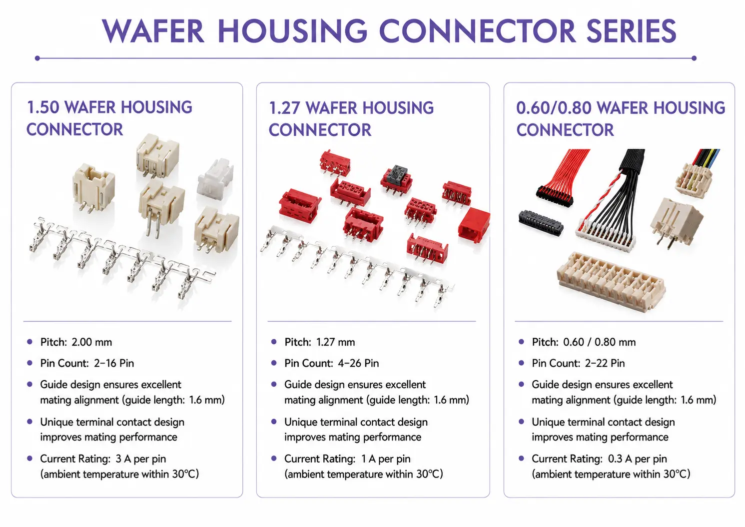
Wafer Housing Connectors
Wafer housing connector projects may be reviewed for PCB-to-wire interfaces, including source-material examples such as 0.60 / 0.80, 1.27, and 1.50 wafer housing connector references.
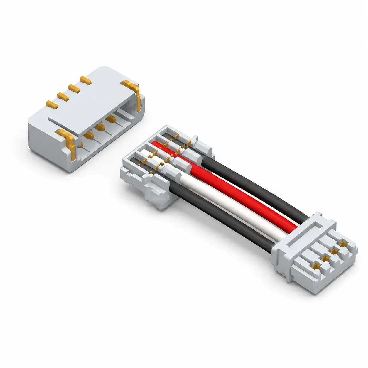
IDC and Crimp-Style Assemblies
Source materials include a 0.8mm pitch 4-position crimp-style IDC connector assembly reference for compact internal electrical interconnects.
Applications
Application scenarios for PCB-to-wire interfaces
Internal device wiring
PCB-to-wire connection between a board and internal cable or harness-side interface.
Industrial control equipment
Connector support for internal control boards, device wiring, and equipment-level interconnect projects.
Display and lighting modules
Internal connector review for display, lighting, and module-level wiring layouts.
Testing and measurement devices
Wire-to-board interface review for compact equipment where reliable internal wiring is required.
Engineering support
LinkManu can review drawings, mating direction, position count, pitch, and housing or header requirements before quotation. Selected fit-style connector options may be reviewed when a customer provides drawings or target connector information.
Structure and interface review
For wafer, header, housing, IDC, or crimp-style projects, the review should confirm the PCB-side connector, mating cable side, and assembly constraints before sampling.
Project validation support
Project review should be based on approved drawings, fit checks, and sample validation. Final suitability depends on the drawing, mating requirement, and project-specific validation.
Related Products
Connector categories often reviewed together
FAQ
Wire-to-board connector FAQs
What is the difference between wire-to-board connectors and board-to-board connectors?
Wire-to-board connectors connect a PCB to a wire, cable, or harness-side interface. Board-to-board connectors connect two PCBs together and should be handled on the Board-to-Board Connectors page.
Can LinkManu review wafer housing connector projects?
Yes. Source-material examples include wafer housing connector references, and LinkManu can review selected fit-style connector options when project drawings or target connector information are provided.
Can you review PCB connectors for wire-to-board projects?
Yes. LinkManu can review PCB connectors for wire-to-board projects when the drawing, pitch, position count, housing or header requirement, and mating cable-side information are provided.
Does this page cover cable assembly manufacturing?
This page focuses on PCB-side wire to board connector selection. For wire processing, cable length, terminal crimping, harness routing, or assembly manufacturing, please use the Cable Assemblies page.
Can high-current wire-to-board projects be reviewed?
High-current wire-to-board projects may be reviewed, but power-focused projects should remain under Power Connectors. Final suitability depends on the drawing, mating requirement, and project-specific validation.
What information should I send for a wire to board connector RFQ?
Please send the target connector type, pitch, position count, mating direction, housing or header information, cable-side requirement, drawing files, and expected application environment.
RFQ Support
Need help selecting a wire-to-board connector?
Send your drawing, target connector information, pitch, pin count, and mating requirements. LinkManu will review suitable connector options for your PCB-to-wire project.