
Card Edge Connector Engineering Guide
Card Edge Connector Selection Guide: Specs and RFQ Checks
A card edge connector should be selected from the PCB interface outward, not from a catalog description inward. The contact layout, board thickness, edge geometry, current path, retention method, and operating environment all affect whether the interface is suitable. A part that appears close on a product page may still create insertion, alignment, wear, or qualification problems when compared with the actual drawing.
This card edge connector selection guide gives engineers and technical buyers a practical review sequence. It avoids assuming a standard pitch, plating system, board thickness, or test level. Those details should come from the customer drawing, original sample, approved specification, or project test plan.
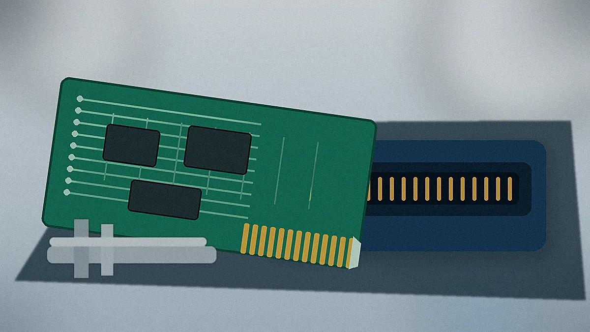
Engineering decision: do not release a connector for quotation until the PCB edge drawing and the intended mating conditions are available. A part number alone rarely defines the full interface.
Start With the PCB Edge, Not the Connector Catalog
The board edge is the fixed reference for the selection. Begin with the pad pattern, contact count, board thickness and tolerance, edge length, bevel, keying features, and any keep-out areas near the slot. If the board has already been laid out, the connector must be checked against that geometry. If the layout is still open, connector availability and manufacturing constraints should be reviewed before the edge footprint is frozen.
A frequent procurement risk is treating pitch and position count as independent fields. They are linked to total edge length, housing width, contact arrangement, and polarization. Changing the pitch can force a different pad pattern or mechanical envelope. Changing the position count can affect insertion force and retention. The drawing review should therefore confirm the complete interface rather than matching only one catalog value.
| Review area | Evidence to provide | Engineering or sourcing risk if omitted |
|---|---|---|
| PCB edge geometry | Board drawing with thickness, tolerance, bevel, slot, and keying details | The board may not enter correctly, may sit at the wrong depth, or may load the contacts unevenly. |
| Contact layout | Pad pitch, position count, single- or dual-sided arrangement, and unused positions | A near-match can create shifted contacts, incorrect circuit mapping, or an unsuitable housing length. |
| Electrical duty | Current per contact, signal type, grounding plan, and any controlled-impedance requirement | The supplier cannot judge terminal design, heat rise checks, or signal review from position count alone. |
| Mechanical duty | Mating frequency, retention method, mounting constraints, and service access | Insertion force, wear, or board movement may be overlooked during sample approval. |
| Environment and compliance | Operating conditions, required material controls, test plan, and document list | Samples may pass a basic fit check but still lack the evidence needed for production qualification. |
Choose Pitch and Position Count as a Complete Interface
Pitch selection starts with space, circuit density, assembly tolerance, and the electrical function of the contacts. A finer arrangement may support a compact layout, but it also leaves less room for pad, housing, and alignment variation. A wider arrangement may simplify inspection or routing, yet it can enlarge the connector and PCB edge. Neither direction is automatically better; the correct choice depends on the drawing and the application.
Position count should be checked against both the electrical circuit list and the mechanical envelope. Include grounds, spare circuits, reserved positions, and any polarization feature in the review. For available family options, use the Card Edge Connectors for PCB Edge Slot Interfaces page as a starting point, then confirm the required configuration against the project files.
Board Thickness, Bevel, and Insertion Depth
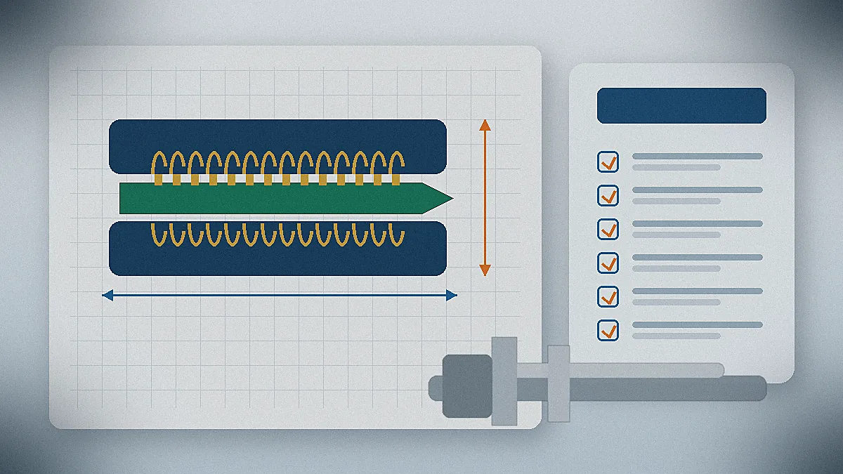
Board thickness is not a nominal label to copy into an RFQ. The tolerance, local finish build-up, bevel geometry, and final insertion depth all influence how the edge enters the slot and where the contacts land on the pads. Ask the board fabricator for the controlled values and compare them with the connector drawing. Where the edge is keyed or notched, verify the datum used by both drawings so that the slot and contact pattern are referenced from the same feature.
Treat Materials and Plating as Drawing-Controlled Inputs
Terminal material, contact finish, plating thickness, and housing material should not be filled in from habit. They affect contact force, wear behavior, corrosion exposure, processing conditions, and compliance documentation. The safe procurement approach is to state the required performance and the governing drawing, then ask the supplier to identify the proposed material system and provide supporting documentation.
For a replacement or compatible-alternative project, provide the original part reference, mating board details, available samples, and the reason for the change. Do not describe the new part as a drop-in replacement until fit, pin mapping, retention, material requirements, and sample results have been checked. Similar appearance is not evidence of equivalence.
Procurement check: request a controlled drawing and revision number with the quotation. Material or plating descriptions in an email are not a substitute for a released specification.
Plan Sample Validation Before Production Release
Sample approval should reproduce the real assembly conditions as closely as practical. A loose board inserted by hand may hide alignment or retention problems that appear in the final enclosure. Use the production-intent PCB, mounting hardware, surrounding components, and expected insertion direction. Record any abnormal force, uneven engagement, contact wipe concerns, board movement, or interference.
Electrical and environmental checks should follow the application requirement rather than a generic test list. Depending on the project, the review may include contact resistance, temperature rise, dielectric or hi-pot checks, signal integrity, vibration, salt spray, or other environmental tests. The RFQ should identify which results are required from the supplier, which may be arranged through an external laboratory, and what acceptance criteria control the decision.
- Compare the sample and controlled drawing before functional testing.
- Confirm insertion and extraction behavior in the actual board mounting arrangement.
- Check contact landing and pad wear after repeated handling appropriate to the project.
- Review test reports for part number, revision, sample quantity, method, conditions, and acceptance result.
- Resolve any mismatch between the datasheet, drawing, sample, and report before volume approval.
Check Supplier Process Scope and Documentation
Supplier capability matters when the project needs a new housing, terminal adjustment, tooling change, or controlled production release. Company materials provided for this article list tooling, stamping, injection molding, assembly, and inspection capabilities. Confirm which steps apply to the quoted connector, which operations are internal or external, and how changes are controlled after sample approval.
The same evidence rule applies to engineering support. Company materials reference Pro-E modeling, Moldflow analysis, terminal stress analysis, and signal-integrity simulation. These are project-dependent resources, not automatic deliverables. State the design question that needs analysis and request the proposed scope, input data, output format, and responsible reviewer.
Company materials also reference IATF 16949 and ISO 14001. During supplier qualification, request current certificates, scope, issuing body, and the manufacturing site covered. A certification name in a presentation should not be used as proof that every connector or production line is qualified for a specific end market.
Build an RFQ Package That Can Be Reviewed
A useful RFQ lets engineering and procurement review the same evidence. Avoid sending only a target price and a catalog screenshot. At minimum, include the PCB edge drawing, circuit count, intended application, annual or project quantity, schedule, sample requirement, material or compliance constraints, and the list of documents needed for approval.
| RFQ item | What the supplier should confirm |
|---|---|
| Interface files | Connector drawing match, PCB thickness range, contact position, keying, and mounting method |
| Electrical requirements | Proposed contact system, circuit allocation, applicable ratings, and any required analysis or testing |
| Materials and finish | Proposed terminal, plating, and housing specifications tied to a controlled document |
| Samples and qualification | Sample configuration, lead-time basis, test responsibility, report availability, and change control |
| Production support | Applicable process steps, inspection plan, traceability, packaging, and documentation supplied with orders |
What to Confirm Next
Before choosing a part number, confirm the PCB drawing, pitch and position count, mating height or insertion depth, board thickness and tolerance, current and signal requirements, retention method, operating environment, test documentation, and supplier process scope. Where the project uses a specific form factor, compare the requirements with the 3U card edge connector guide. For adjacent connector families, review all LinkManu product categories.
The value of a card edge connector selection guide is not a universal part recommendation. It is a review path that exposes missing inputs before samples, tooling, or production quantities are committed.
Card Edge Connector Selection FAQ
What information is needed to select a card edge connector?
Provide the PCB edge drawing, pitch, position count, board thickness and tolerance, keying, electrical duty, environment, and required qualification documents.
Can a connector be selected from pitch alone?
No. Position count, board thickness, contact arrangement, insertion depth, keying, retention, and material requirements must also match.
How should a replacement connector be evaluated?
Compare drawings, pin mapping, PCB fit, retention, materials, samples, and test results. Do not assume equivalence from appearance or pitch.
Which tests should be requested?
Use the end-application requirements. Define the test method, conditions, acceptance criteria, report format, and whether testing is internal or external.
Send Your Connector Requirement
Share the PCB edge drawing, BOM, target application, sample requirement, and documentation checklist for an engineering and RFQ review.