
High-Speed Connector Selection
PCI-6513 Connector Selection: How to Choose the Right High-Speed Connector
Effective pci-6513 connector selection starts with the channel, the mating pair, and the drawing package. A connector that looks close in a catalog can still fail the project if the pinout, host-board footprint, plug height, or documentation set does not match the backplane design. For engineers and technical buyers, the safer question is not “does it fit?” but “can this connector be verified against the protocol, mechanical envelope, and validation plan?”
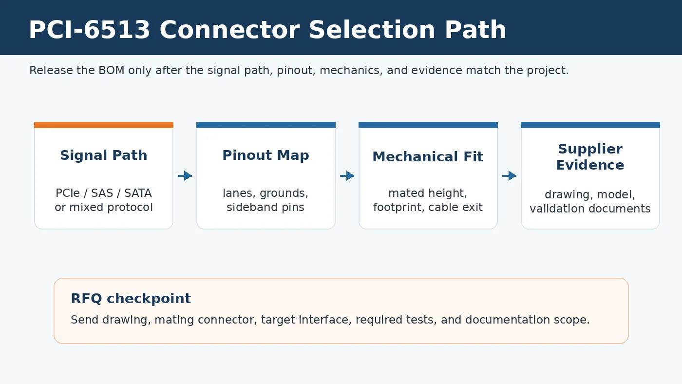
Engineering takeaway: treat the PCI-6513 connector as part of the high-speed channel. Confirm the drawing, lane map, mating height, plug and receptacle pairing, and available test documentation before approving a production substitute.
Start With the Channel, Not the Part Number
A PCI-6513 connector is commonly discussed in the same purchasing workflow as high-speed backplane and storage-interface connectors. That does not make every similar board connector acceptable. The first check is whether the part is intended for the same signal path and mechanical interface that your system uses. If a buyer substitutes a visual match without engineering review, the risk usually appears later: link training becomes unstable, the drive is not detected, or the mechanical assembly loads the solder joints in a way the layout team did not expect.
For high speed connector selection, the connector should be reviewed as one element of the full channel: transmitter, PCB routing, connector body, mating plug, and receiver. A small change in contact geometry or ground placement may not matter in a low-speed control harness, but it can change the return path in a high-speed link. That is why the supplier drawing and the customer layout should be checked together, especially when the project involves PCIe, SAS, SATA, or a mixed-protocol backplane.
What to check before approving a PCI-6513 connector
- Confirm whether the connector is being used for host-board receptacle, cable assembly plug, or a mated system.
- Compare the supplier drawing with the customer PCB footprint before sample ordering.
- Check the PCI-6513 pinout against the required protocol mapping instead of relying on position count alone.
- Ask what validation evidence is available for the target application, including signal integrity, mechanical retention, and environmental checks when required.
- Separate catalog claims from project-specific requirements. Current rating, impedance target, plating, and temperature conditions should come from the drawing, datasheet, or validation plan.
Use SFF Compliance as a Boundary, Then Verify the Drawing
The uploaded source material points to SFF documents as the main standards context for this topic. In practical terms, SFF references help define the mechanical envelope, the plug and receptacle relationship, and the interface expectations for multi-application storage connectors. They are useful boundaries, but they do not replace project review. A supplier still needs to show that the exact variant being quoted matches the drawing, footprint, and mating partner you intend to use.
For this reason, LinkManu’s broader high-speed connectors for PCIe, SAS and board-to-board signal links page is the correct internal reference for this article. It frames PCI-6513 as part of a wider high-speed connector sourcing discussion, not as a generic replacement promise. If the project needs a compatible alternative, the RFQ should include the original drawing, mating connector details, sample photos, and the target interface requirement.
| Selection Area | Engineering Check | Procurement Risk if Skipped |
|---|---|---|
| Protocol fit | Confirm whether the application expects PCIe, SAS, SATA, or a mixed-protocol backplane. | A mechanically similar part may not support the required signal mapping or sideband functions. |
| Pinout review | Compare the PCI-6513 pinout with the customer schematic and supplier lane assignment table. | Lane swaps, missing detect pins, or unplanned no-connect positions can block system bring-up. |
| Mated height | Check the fixed connector, free connector, board stack, and cable exit together. | A plug and receptacle may appear compatible but still create partial mating or assembly stress. |
| Documentation | Request drawing, footprint, 3D model, material information, and available test reports. | The buyer may approve a BOM before the design team can confirm manufacturability or validation scope. |
Pinout Review Is Where Many Selection Errors Start
The PCI-6513 pinout should be treated as a design input, not a note at the end of a datasheet. Differential pairs need a stable return path, and sideband or management contacts may be required for detection, monitoring, or later firmware features. If the design team only checks the number of positions, it can miss the exact issue that decides whether the system trains, detects the drive, or passes its own validation plan.
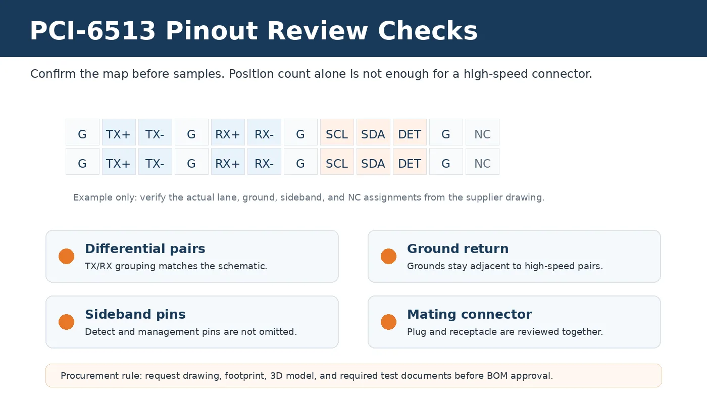
A good review also checks what is not shown clearly. Are unused positions truly no-connects, or are they reserved for a later configuration? Are detect and management pins required by the system architecture? Does the receptacle orientation match the cable exit and service path? These questions are not paperwork. They prevent a sample from passing a bench fit check while still failing in the chassis.
Pinout and sideband questions to ask
- Which lanes are used by the current system configuration, and which lanes are intentionally unused?
- Where are the ground return contacts relative to the high-speed differential pairs?
- Does the design require present-detect, management bus, activity indication, or other sideband signals?
- Has the supplier provided a footprint that matches the customer PCB layout constraints?
- Will a future firmware or platform revision need pins that the first build does not use?
Mechanical Pairing Can Be as Important as Electrical Fit
A PCI-6513 connector selection mistake can be mechanical even when the electrical drawing looks acceptable. Fixed and free connectors must be evaluated as a pair. If the receptacle height, plug geometry, or cable-exit direction is wrong, the assembly may force a bend radius that blocks airflow or adds stress near the solder joints. In compact storage systems, the wrong exit direction can also make service work harder because the cable path competes with drive trays, fans, or stiffeners.
Do not approve a low-profile or right-angle variant based only on a catalog description. Ask for the mechanical drawing and 3D model, then check clearance, insertion direction, hand-access, and service removal. If the enclosure is already fixed, the connector decision should be reviewed with the chassis model, not just the PCB layout. This is especially important when the buyer is trying to replace an original connector after the mechanical design is already locked.
| Mechanical Point | What to Confirm | Why It Matters |
|---|---|---|
| Mounting style | Vertical, right-angle, straddle, or other board-mount requirement. | The wrong style can force PCB or chassis changes late in the project. |
| Mated height | Receptacle height, plug height, board stack, and allowed tolerance. | Partial mating can create intermittent opens or solder-joint stress. |
| Cable exit | Direction, bend space, airflow path, and service access. | A working electrical choice can still fail the assembly process. |
| Retention | Requested insertion and extraction behavior for the actual chassis use case. | Retention needs differ between lab prototypes, serviceable systems, and high-vibration equipment. |
Supplier Review: What Evidence Should Procurement Request?
The uploaded project facts allow a cautious supplier-capability discussion. Company materials describe engineering support such as Pro-E modeling, Moldflow analysis, ABAQUS terminal stress analysis, and SI simulation, but the scope should be confirmed per project. They also list process steps including design engineering, mold development, injection molding, post-processing, product assembly, and inspection before shipment. That does not mean every PCI-6513 project receives every step. It means procurement should ask which steps apply to the actual connector and RFQ scope.
For a high-speed connector, useful supplier evidence often includes a controlled drawing, recommended PCB footprint, 3D model, material and plating information, sample availability, and available test documentation. If the buyer needs impedance, temperature rise, hi-pot, insertion/extraction force, salt spray, vibration, or environmental testing, those should be requested as project requirements rather than assumed. Some tests may be arranged depending on the product and validation need.
Documents to include in the RFQ package
- Customer drawing or original part drawing, including pitch, position count, mated height, and mounting style.
- Target application and protocol requirement, including whether the system is PCIe, SAS, SATA, or mixed protocol.
- PCI-6513 pinout or schematic excerpt showing lane use, grounds, sideband pins, and no-connect positions.
- Mechanical constraints such as chassis clearance, cable exit direction, board thickness, and service access.
- Required validation documents, such as dimensional report, material information, SI data, or mechanical test report, if the project needs them.
FAQ
Is a PCI-6513 connector just a board-to-board connector?
No. It should be reviewed against the target interface, pinout, mated pair, and validation plan. A generic board connector may fit visually but still fail the signal or mechanical requirement.
Can I approve a connector from position count alone?
No. Position count is only one check. Confirm the lane map, ground placement, sideband pins, footprint, and mating connector.
What should I send for a PCI-6513 connector RFQ?
Send the drawing, pinout, target protocol, mating height, cable-exit requirement, sample photos if available, and any required test documentation.
Conclusion and Next Step
A publishable PCI-6513 guide should not promise a universal replacement or fixed performance value. The right next step is to confirm the drawing, pitch or position requirement, mating height, PCI-6513 pinout, current and signal requirements, environment, and documentation scope. If the project is already in layout, add the PCB footprint and chassis clearance model so the supplier can review electrical and mechanical fit together.
Send Your Connector Requirement
Share your drawing, BOM, target application, or technical requirements. LinkManu can review connector fit, sample options, documentation needs, and RFQ readiness before final selection.

Technical Content Reviewed by LinkManu Engineering Team
This article was reviewed for connector selection logic, unsupported claim removal, and RFQ-ready engineering checks.