
Card Edge Connector Selection
How to Choose 3U Edge Connectors for PCB Design
Choosing 3u edge connectors is not only a part-number search. In a 3U PCB project, the connector has to fit the board edge, the slot, the enclosure, the mating direction, the current map, and the service plan. If one of those items is assumed instead of checked, the connector can pass a desk review and still create problems during assembly, testing, or field replacement.
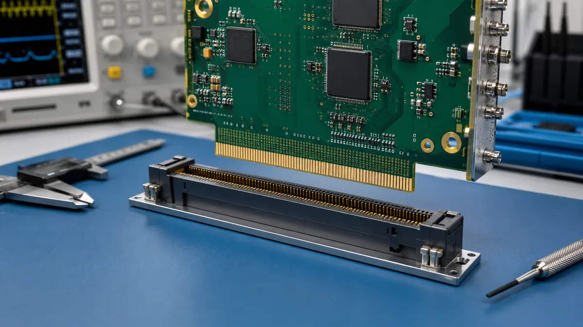
This guide keeps the selection work practical. Instead of treating all card edge parts as interchangeable, it shows what engineers and sourcing teams should confirm before the PCB layout, sample order, and supplier review move too far forward.
Start With the 3U Mechanical Envelope
The first risk is usually mechanical, not electrical. A connector that looks acceptable in a catalog can still fail the project if the board thickness, slot depth, connector height, card guide, retention method, or insertion path does not match the actual chassis. For 3U systems, this check should happen before the board edge and keep-out zones are frozen.
Ask the design team to mark the connector area on the drawing, including the gold-finger edge, component keep-out, mechanical support, and expected mating direction. If the module will be removed during service, also check how much board flex is acceptable during insertion and extraction. A connector that works in a lab fixture may be too easy to misalign in a rack or embedded enclosure.
Engineering check: confirm board thickness, mating height, slot orientation, keep-out area, insertion path, retention method, and whether the module is field-replaceable. Do not approve the connector from pitch and position count alone.
Match Pitch and Contact Layout to the Real Circuit
Edge connector pitch affects routing density, contact spacing, soldering tolerance, and the amount of room available for ground return paths. A smaller pitch may help fit the connector into a compact 3U board, but it can also tighten PCB fabrication and inspection requirements. A larger pitch may give the layout more margin, but it may consume board edge length that the enclosure cannot spare.
For card edge connector selection, the useful question is not “which pitch is common?” The better question is “which pitch leaves enough room for the power contacts, signal contacts, ground strategy, and manufacturing tolerance in this design?” If the board carries both power and signals through the same edge interface, ask for a contact map before choosing the housing.
| Selection Item | What to Confirm | Why It Matters |
|---|---|---|
| Pitch and contact density | Confirm the required contact count, routing room, PCB fabrication tolerance, and inspection method. | A dense layout can save edge length but may reduce tolerance margin and make rework harder. |
| Power contact allocation | Map current paths and confirm the supplier’s current-rating conditions from the datasheet. | Current rating depends on contact design, temperature rise, grouping, and test conditions. |
| Signal contact allocation | Check ground return placement, pair routing, and any controlled-impedance requirements. | The connector can become a discontinuity if the pin field ignores the signal path. |
| Board edge finish | Confirm the gold-finger finish, bevel, edge quality, and inspection criteria with the PCB supplier. | The board edge is part of the mating system, not a cosmetic PCB detail. |
| Service cycle requirement | Decide whether the board is factory-mated once, tested repeatedly, or removed in the field. | Mating-cycle expectations affect plating, retention, and supplier documentation needs. |
If the project includes high-speed signals, do not rely on a generic connector category name. Ask whether the supplier can provide the relevant electrical model, layout guidance, or test documentation for the selected series. If that documentation is not available, treat the connector as a project risk until the signal path is reviewed.
Choose the Connector Type Around Assembly and Service
Different 3U connector types solve different layout problems. A right-angle connector may fit a backplane architecture, while a vertical connector may suit a motherboard-to-module arrangement. A straddle-style design can reduce some routing detours, but it usually makes board thickness control and soldering process review more important.
Procurement should not treat these types as simple alternatives. The assembly process, test fixture, card guide, and service access can change with the connector style. If the connector forces the board into an awkward insertion angle, or if the enclosure gives technicians no clean way to remove the module, reliability risk shifts from the component to the system design.
- Right-angle orientation: useful when the daughter card enters a backplane or main board from the side. Check board support and solder-joint stress during insertion.
- Vertical orientation: useful when the module mates downward into a board. Check component height, access for inspection, and whether the card guide controls alignment.
- Straddle-style mounting: useful when the connector grips the PCB edge from both sides. Check board thickness tolerance, pad design, coplanarity, and reflow control.
- Single-sided or dual-sided contacts: useful for different density and force targets. Check whether the total mating force is acceptable for the board and the service procedure.
Check the Environment Before Approving the Plating
Plating should be tied to the actual duty cycle and environment. A board used in a controlled cabinet does not face the same risk as a module exposed to humidity, vibration, frequent replacement, or corrosive industrial air. Without that context, the plating discussion becomes a price comparison instead of a reliability decision.
Ask for documentation that matches the installation conditions: contact resistance test method, insulation resistance, dielectric withstand test conditions, humidity exposure, thermal cycling approach, and mating-cycle rating. If the supplier only provides a headline rating without test conditions, the engineering team should treat it as incomplete information rather than an approval basis.
Procurement check: request the datasheet, drawing, material declaration, plating description, test report summary, and any application notes before locking the RFQ. The risk is not only whether the connector can be bought, but whether the selected version can be verified for the project conditions.
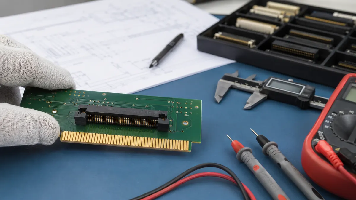
Review Supplier Capability, Not Only the Connector Drawing
The connector drawing tells you the target geometry. It does not prove that every shipment will hold the same process window. For 3U projects with tight mechanical fit, sourcing should ask how the supplier controls tooling, stamping, injection molding, assembly, and inspection. These capabilities matter because contact geometry, housing consistency, and assembly alignment all affect the final mating interface.
LinkManu’s uploaded capability facts include tooling, stamping, injection molding, and assembly, with certification references including IATF 16949 and ISO 14001. For a buyer, the practical next step is to request the supporting certificate files and project-specific inspection documents, then compare them with the drawing requirements. A certificate is useful, but it does not replace part-level verification.
When reviewing Card Edge Connectors for PCB Edge Slot Interfaces, use the product page as the starting point, then move into the project details: board thickness, pitch, mating height, contact count, current map, environment, sample plan, and documentation requirements. If the project needs a modified housing, special keying, or a non-standard contact layout, the supplier discussion should happen before the PCB edge is finalized.
When a Standard Part Is Not Enough
A standard card edge connector is usually the fastest route when the board, slot, contact count, pitch, and environment fit an existing series. The warning sign appears when the team starts changing the PCB, enclosure, or test procedure just to make a catalog part fit. At that point, the cheaper-looking connector can create extra cost in layout work, fixture changes, or long-term service handling.
Consider a custom or modified connector discussion when the project needs special polarization, a tighter mechanical envelope, a dedicated power-and-signal contact map, unusual retention, or documentation beyond the standard datasheet. For teams comparing suppliers, LinkManu’s guide to choosing a custom connector design firm can help frame the capability review before samples are requested.
Practical Selection Checklist for 3U Edge Connectors
- Confirm the PCB drawing, board thickness, gold-finger finish, edge bevel, and connector keep-out zone.
- Define the mating direction, insertion path, card guide, retention method, and service access.
- Map power, signal, and ground contacts before selecting pitch or contact count.
- Request current-rating conditions, plating details, and environmental test documentation.
- Check whether the part is factory-mated once, tested repeatedly, or replaced in the field.
- Review supplier capability for tooling, stamping, molding, assembly, inspection, and traceability.
- Ask whether samples, drawings, and inspection documents can be provided before RFQ approval.
Next Step Before You Send the RFQ
Before approving 3u edge connectors for a PCB design, prepare the drawing, pitch target, mating height, board thickness, current map, signal requirements, operating environment, mating-cycle expectation, and documentation needs. With those items ready, the supplier can review the connector fit instead of guessing from a short part description.
FAQ
Are all 3U edge connectors interchangeable?
No. Pitch, board thickness, contact layout, mating direction, and retention details must match the actual PCB and enclosure.
What should I confirm before choosing edge connector pitch?
Confirm contact count, routing space, current map, signal return paths, PCB tolerance, and inspection capability.
When should procurement ask for a custom connector review?
Ask when a catalog part forces board, enclosure, keying, contact layout, or documentation compromises.
What files help LinkManu review a 3U connector project?
A PCB drawing, target pitch, mating height, board thickness, current rating needs, environment, and test documentation requirements.
Send Your Connector Requirement
Share your drawing, BOM, target application, or technical requirements. LinkManu can review connector fit, sample options, documentation needs, and RFQ readiness before final selection.

Technical content reviewed by LinkManu Engineering Team
Prepared by LinkManu Editorial Team for B2B connector engineers, sourcing teams, and product development projects. Updated 2026.