
Connector Selection Guide
5 Pin Connector Wiring: Engineering Checks Before You Lock the Pinout
5 pin connector wiring should start with the mating-face drawing, not with the assumption that five contacts follow one universal order. The same contact count can appear in DIN-style plugs, M12-style industrial connectors, automotive circular housings, rectangular housings, and rugged circular shells. Each family can use different keying, pin numbering, contact size, strain relief, and sealing methods. A wiring plan that ignores those details may pass a quick continuity check and still fail when the assembly is installed.
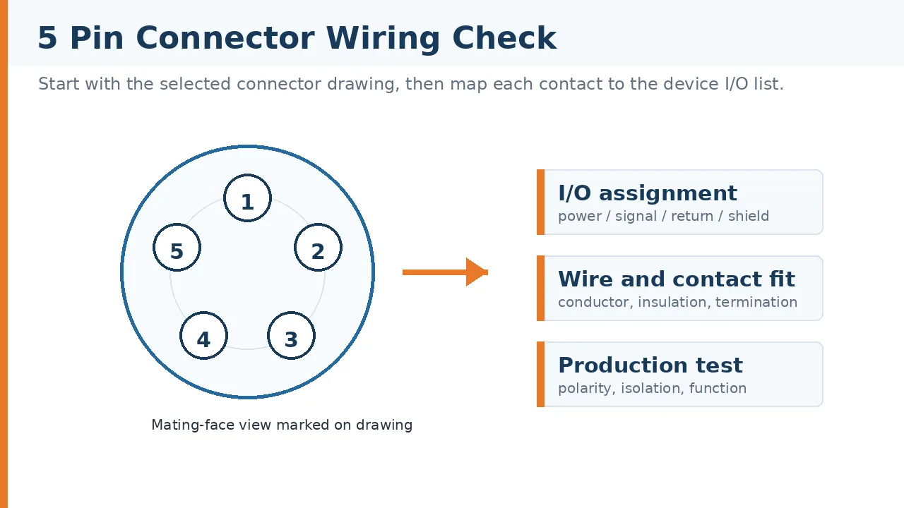
Start With The Pinout, Not The Part Count
A procurement line that says “5-pin connector” is not enough for production. Engineering still needs the connector family, plug or receptacle side, mating-face orientation, pin numbering view, contact termination method, and cable exit direction. If any one of those items is missing, the assembler may wire from the wrong side of the drawing.
The risk is highest when teams replace a connector family during sourcing. A DIN-style drawing cannot be copied into an M12-style or rectangular connector without a crossover review. Even when the devices use the same number of contacts, the keying position and numbering order may change the functional result. For 5 pin connector wiring, the safe question is not “does it have five pins?” but “does each physical cavity match the intended signal, return, shield, or power path on the mating connector?”
Engineering check: release the wiring diagram only after the plug-side and receptacle-side views are both marked. If the supplier drawing shows the solder side but production checks the mating side, the inspection fixture can approve the wrong harness.
Common Wiring Assumptions That Create Field Problems
Most 5 pin connector wiring errors are simple at the bench and expensive in the field. They usually come from a copied drawing, an incomplete BOM description, or a test plan that checks continuity but not the actual function under load.
- Pin 1 treated as universal: the first numbered contact is not automatically positive supply, signal, or ground. It must be mapped against the device I/O list.
- Plug and socket views mixed: the same physical interface can look mirrored depending on whether the drawing is shown from the mating face or the termination side.
- Shield path left undefined: a shielded cable only helps when the connector body, drain wire, or termination method gives the shield a controlled path.
- Power and signal sharing ignored: mixed circuits in one housing need a check for contact rating, spacing, heat, and noise sensitivity before the pinout is approved.
- Field termination treated like factory assembly: a connector wired in the field may depend on installer discipline, tool control, and clear labeling more than a molded cable assembly does.
These checks sound basic, but they decide whether the first production lot is repeatable. A drawing that does not define orientation, shielding, wire color, cavity number, and test points is still a draft, even if the connector part number is already selected.
What To Confirm Before Drawing A 5 Pin Connector Wiring Diagram
The wiring diagram should be the output of the selection process, not the starting guess. Before assigning the five contacts, engineers and buyers should confirm the electrical load, mechanical fit, environment, and termination process. If one of those inputs is unknown, write it as a question for the supplier rather than filling the gap with a catalog assumption.
| Selection Area | What To Check | Risk If Skipped |
|---|---|---|
| Electrical assignment | Map each contact to power, signal, return, shield, or unused position from the device I/O list. | A copied pinout can route the wrong function to the board or controller. |
| Connector orientation | Confirm mating-face view, termination-side view, key position, and numbering direction. | Harness inspection may approve a mirrored wiring layout. |
| Wire and contact fit | Check whether the selected contact accepts the required conductor size and insulation type. | Loose or damaged terminations can become intermittent after handling or vibration. |
| Panel and cable routing | Review backshell direction, bend space, strain relief, and whether the connector is cable, panel, or PCB mounted. | The cable may be forced into a tight bend or twisted during mating. |
| Production test | Define continuity, insulation, polarity, and functional checks against the approved pinout. | A harness can pass a simple point-to-point test while still failing in the equipment. |
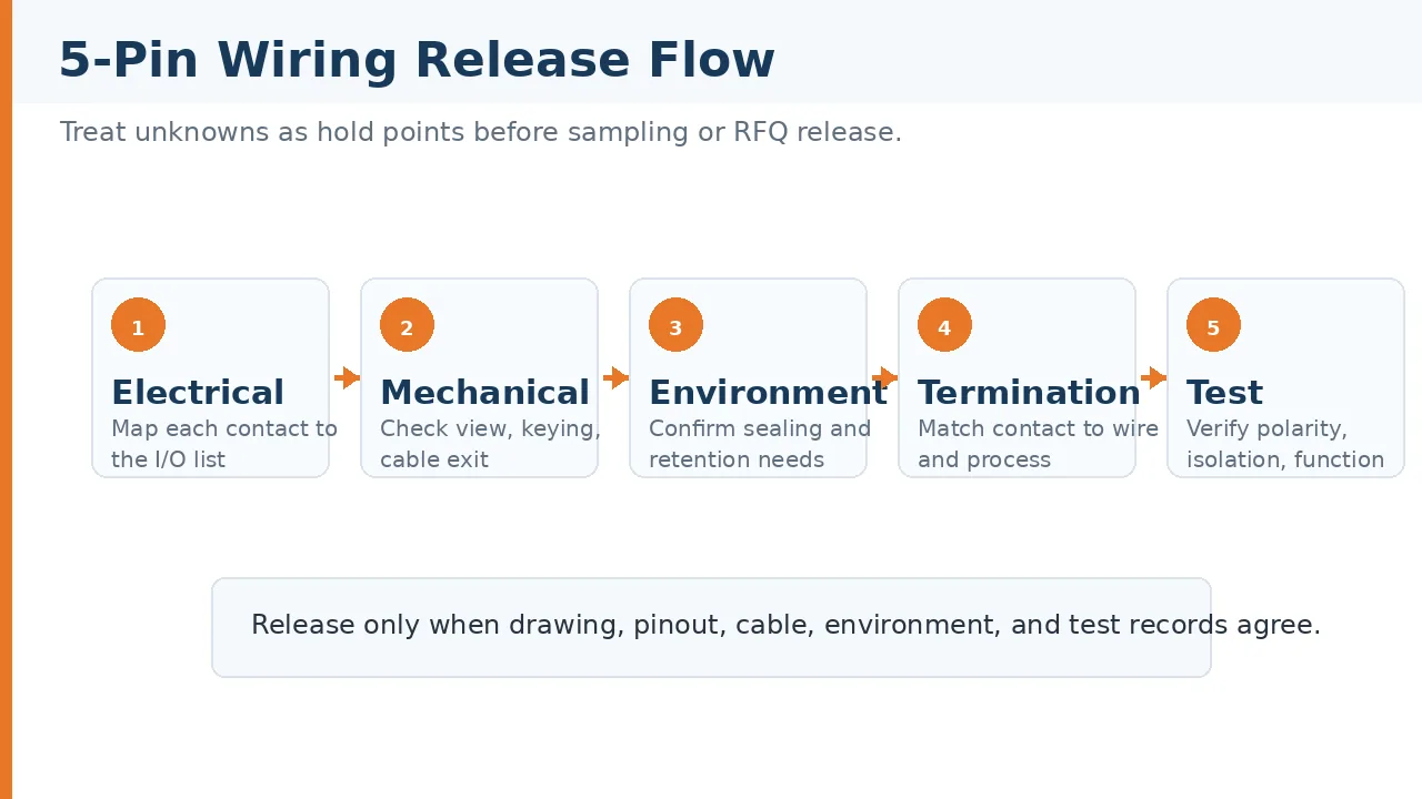
When Environment Changes The Wiring Decision
A connector that works on a bench can still be the wrong choice for the installed machine. Vibration, moisture, temperature cycling, washdown, cable movement, and chemical exposure all change how the wiring should be terminated and protected. The practical issue is not only the connector body; it is the complete cable entry, contact retention, housing material, sealing interface, and inspection method.
| Field Condition | Engineering Question | Procurement Check |
|---|---|---|
| Vibration or moving cable | Will the contact, crimp, solder joint, or field terminal keep retention under movement? | Ask for the intended termination method and sample inspection criteria. |
| Moisture or washdown | Does the seal match the cable jacket, entry diameter, and mating condition? | Do not rely on the connector shell rating without confirming the assembled cable. |
| Mixed power and signal | Are spacing, heat, shielding, and return paths suitable for the actual circuit mix? | Request a reviewed pin assignment, not just a catalog image. |
| Service replacement | Can a technician identify orientation and pinout without opening the equipment? | Use clear labels, keyed housings, and controlled replacement drawings. |
For lower-position projects, the same discipline applies. A two-contact design may look simpler, but polarity, housing keying, current path, and installation environment still need review. That is why selection teams often compare 5-pin work with 2 pin connector types when building a family-level connector rule for a product platform.
Connector Families That Need Separate Wiring Checks
The family name tells you what to verify next. It does not remove the need for a project drawing. The table below keeps the focus on wiring logic, not on claiming that one connector type can replace another.
| Connector Family | Where It Often Appears | Wiring Judgment |
|---|---|---|
| DIN-style 5-pin connector | Audio, control, and legacy equipment interfaces | Confirm the exact pin arc, plug or socket view, and whether the application expects a known legacy pinout. |
| M12-style 5-pin connector | Industrial sensors, actuators, and machine I/O | Do not assume another machine builder’s pin assignment applies. Confirm the I/O list and field termination process. |
| Automotive circular connector | Vehicle sensors, equipment harnesses, and exposed cable runs | Check sealing, vibration retention, wire exit direction, and crimp control before approving the harness. |
| Rectangular multi-pin housing | Board, panel, and compact equipment layouts | Review cavity numbering and latch direction because the wiring order can differ from a circular layout. |
| Rugged circular shell | Harsh environment or high-retention equipment | Confirm insert arrangement, shielding path, backshell, and documentation requirements for the exact build. |
EC5 is sometimes raised in search results around this topic, but it should not be treated as the same problem as 5 pin connector wiring. EC-style battery connectors are usually discussed for high-current single-path applications. A true five-contact signal, power, or hybrid interface needs its own pinout, contact rating, insulation, and environmental review from the selected connector drawing.
How LinkManu Reviews A 5-Pin Wiring Request
A useful supplier review starts with the files that reduce ambiguity: mating connector drawings, device I/O list, cable construction, expected environment, installation direction, required test records, and any sample or RFQ constraints. Without those inputs, a supplier can only discuss options. With them, the review can identify where the pinout, contact choice, housing, and assembly process need adjustment.
LinkManu’s available manufacturing capabilities include tooling, stamping, injection molding, and assembly. Those capabilities matter when a 5-pin project needs a custom housing detail, adjusted contact layout, or repeatable cable assembly process. Quality documentation also references IATF 16949 and ISO 14001, which are relevant when buyers need controlled process records instead of only a loose component quote.
For a broader view of connector families that can be reviewed against a project pinout, see the LinkManu Products overview. Use that page as a starting point, then narrow the request with drawings and operating conditions before treating any wiring plan as production ready.
Release Checklist For 5 Pin Connector Wiring
Before a buyer places a production order, the release package should answer a few specific questions. If the answer is missing, treat it as a hold point rather than a minor note.
- Is the drawing view clearly marked as mating side, termination side, plug, or receptacle?
- Does each contact map to a named function in the I/O list?
- Are wire color, conductor size, shield treatment, and cable exit direction defined?
- Has the supplier confirmed termination method and inspection criteria for the selected contact?
- Does the test plan check polarity, isolation, and function, not only continuity?
- Are environment and service conditions written into the RFQ instead of discussed only by email?
The next step is practical: send the drawing, mating height or panel space if relevant, contact assignment, current and signal requirements, environment, and test documentation needs to the supplier before finalizing the BOM. That gives the engineering and procurement teams a wiring decision they can defend during production and after shipment.
Frequently Asked Questions About 5 Pin Connector Wiring
Are all 5-pin connectors wired the same way?
No. Pin count does not define pin numbering, keying, contact rating, shielding, or sealing. Always use the selected connector’s mating-face drawing.
What should be checked first in a 5 pin connector wiring diagram?
Check the view orientation first. A plug-side drawing and a socket-side drawing can look mirrored, which can reverse the finished harness.
Can I reuse a 5-pin wiring diagram from another connector family?
Only after a crossover review. The same five functions may need a different physical cavity order in another housing.
Is an EC5 connector the same as a 5-pin connector?
No. EC5 is usually discussed as a battery-style power connector. It should not be used as a pinout reference for a five-contact interface.
What should I send for supplier review?
Send the mating drawing, I/O list, cable details, environment, installation space, sample quantity, and test documentation requirements.
Send Your Connector Requirement
Share your drawing, pin assignment, cable details, environment, and test requirements. LinkManu can review whether the connector family, wiring plan, and assembly process are ready for sampling or RFQ.

Technical Review
Technical content reviewed by LinkManu Engineering Team. This article is intended for connector selection and RFQ preparation, not as a substitute for the official drawing of the selected connector.