
High-Speed Connector Selection
Small Form Factor Pluggable Connector Selection Guide
A small form factor pluggable connector is not only the metal cage at the edge of a switch or storage board. In a real project, it is part of a controlled high-speed interface that includes the cage, host-board connector, transceiver module, PCB routing, mechanical opening, thermal plan, and supplier documentation. If one of those items is left vague, the risk usually appears later during validation or production approval.
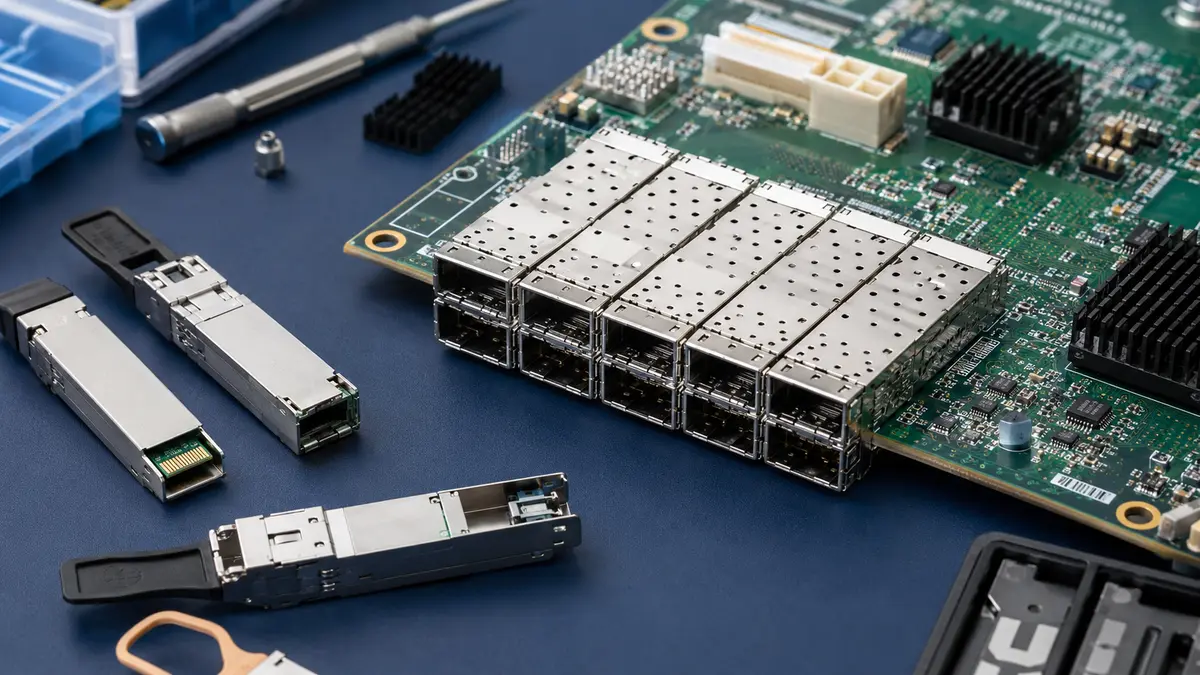
This guide focuses on the checks that matter before an engineer or sourcing team locks a pluggable interface into a design. The uploaded source data supports the topic as an informational selection guide for high-speed connector projects, with available LinkManu facts limited to tooling, stamping, injection molding, assembly, IATF 16949, and ISO 14001. For that reason, the article avoids unsupported claims about exact impedance, current, voltage, temperature, life-cycle count, or guaranteed compatibility.
Engineering note: Treat published standards and supplier datasheets as design inputs, not as a substitute for your own drawing, stack-up, cage footprint, module choice, and validation plan. Exact electrical limits and mechanical tolerances should be confirmed against the current specification revision and the supplier’s controlled documents.
Start With the System Constraint, Not the Connector Name
The phrase small form factor pluggable connector can refer to several related interface families. A buyer may say “SFP,” while the hardware team is actually comparing SFP+, QSFP, or QSFP+ options. Before comparing part numbers, confirm the required data rate family, lane count, media type, panel opening, cage arrangement, thermal space, and the host-board layout rule set.
The first engineering decision is whether the interface is being selected for a new board, a cost-down revision, or a replacement sourcing exercise. A new board can adjust the footprint and routing plan. A cost-down project usually has less freedom: the approved cage outline, latch position, bezel clearance, and module fit may already be fixed. In that case, the RFQ should ask suppliers for drawings and sample verification before any commercial comparison.
Selection Checks Before You Ask for Price
- Form factor: Confirm whether the design needs SFP, SFP+, QSFP, or QSFP+ style hardware, and whether the module ecosystem matches the product plan.
- Port density: Check single-port, ganged, or stacked cage requirements against the panel cutout, heat source location, and service access.
- Board footprint: Ask for the recommended land pattern, mechanical drawing, and keep-out requirements before committing the PCB layout.
- Signal path: Review the complete path from host device to cage, including traces, vias, and any board-level connector in between.
- Documentation: Confirm the supplier can provide drawings, material information, inspection records, and any relevant quality certificates before sample approval.
Where SFP, SFP+, QSFP, and QSFP+ Fit
Form-factor names are useful, but they are not enough for procurement. Two cages with similar names can differ in mechanical details, termination method, thermal option, or supporting documents. Engineers should use the table below as a planning map, then verify the exact project limits against the current specification and supplier datasheet.
| Interface Family | Typical Project Use | Selection Risk to Check | Document to Request |
|---|---|---|---|
| SFP | Lower-speed pluggable optical or copper module interfaces in network and storage equipment. | Do not assume a newer module family will fit the same electrical and mechanical plan. | Host cage drawing, module interface requirement, and approved footprint. |
| SFP+ | Higher-speed single-lane pluggable module applications where the host path must be reviewed carefully. | Signal quality can be affected by routing, via design, cage geometry, and module choice. | Supplier drawing, recommended PCB layout, and applicable SFF document references. |
| QSFP | Multi-lane pluggable applications where port density and cable handling are key concerns. | Panel fit, heat, and cable bend space can become practical limits in dense systems. | Cage outline, bezel recommendation, and module insertion/extraction guidance. |
| QSFP+ | Multi-lane high-speed designs where routing discipline and validation planning matter early. | A small footprint mistake can force a board change or delay sample evaluation. | 3D model, land pattern, material declaration, and quality documentation. |
Signal Integrity Review Starts at the Cage but Does Not End There
The cage and connector assembly is one part of the channel. A clean supplier drawing will not protect the design if the PCB routing, via transition, ground reference, or nearby high-speed connector is poorly planned. For a switch board or storage controller, the practical question is not “Is the cage high speed?” The better question is: “Can the full path from the host device to the module be validated with the available layout, stack-up, and test plan?”
When a project includes board-level high-speed interconnects before the pluggable cage, review those connectors together with the cage interface. A mismatch in the middle of the path can consume margin even if the cage itself is suitable. LinkManu’s related product page on high-speed connectors for PCIe, SAS and board-to-board signal links is the most relevant internal reference for this point.
Layout check: Ask the hardware team to review the host device, PCB stack-up, routing length, via strategy, cage footprint, and any intermediate board-level connector as one channel. Do this before tooling or mass-production sourcing discussions.
Media Choice Changes the Buying Question
The same cage concept may be used with optical modules, direct-attach copper assemblies, or active cable assemblies, but the sourcing conversation changes with the media. Optical modules usually push the review toward module standards, thermal space, and diagnostics support. Copper cable assemblies put more pressure on cable handling, bend space, and host-side channel validation. Active cable assemblies add another supplier-documentation layer because the cable assembly itself becomes part of the active link.
For procurement, the practical mistake is buying the cage as a loose commodity while the module and cable decision is still open. If the product team has not confirmed the module type, operating environment, and service method, keep the RFQ conditional. A clear RFQ should state the target interface family, planned media, expected port arrangement, host-board constraints, and required documents.
Mechanical Fit Can Stop an Otherwise Good Electrical Choice
A pluggable interface sits at the board edge, so mechanical details are not secondary. Cage height, bezel opening, latch clearance, guide rail fit, grounding contact geometry, and insertion path all affect whether the design can be assembled and serviced. In dense port arrays, a cable pull-tab or latch can become a service issue even when the electrical target is acceptable.

Mechanical Review Points
- Confirm the cage outline, pin or press-fit layout, and board-edge relationship against the actual PCB drawing.
- Check the front-panel cutout and latch access with the module and cable installed, not only with the bare cage.
- Review grounding contact geometry and material details with the supplier instead of assuming all cages behave the same.
- Request sample parts early enough for insertion, extraction, and visual inspection before the board layout is frozen.
- Ask whether the supplier can support tooling, stamping, injection molding, and assembly review if a customized cage or related connector part is required.
Standards Help, but Supplier Documents Still Decide the Build
The uploaded research points to the SNIA SFF specification library and SFF documents such as SFF-8431, SFF-8472, INF-8074i, and SFF-8461 as relevant references for this topic. Use those documents to understand scope, interface family, and terminology. Do not convert them into an unsupported claim that every supplier part, module, or host board will work in your exact design.
For a real purchasing file, the supplier package should include the current drawing, recommended PCB footprint, 3D model if available, material and finish information, and quality documentation. If a supplier cannot provide controlled documents, the low unit price may be offset by layout uncertainty, sample delays, or extra incoming inspection work.
| Document or Evidence | Why It Matters | What to Confirm |
|---|---|---|
| Mechanical drawing | Defines cage outline, board relation, and mating details. | Revision, dimensions, tolerance notes, and panel fit. |
| Recommended footprint | Guides PCB layout and manufacturing review. | Termination type, keep-out area, and land pattern revision. |
| Specification references | Shows which SFF document family the part is intended to follow. | Current revision and whether the supplier drawing matches it. |
| Quality certificates | Supports supplier qualification and audit preparation. | Certificate scope, valid date, and relevance to the production site. |
| Sample inspection result | Checks whether received parts match the drawing before approval. | Visual condition, fit, termination quality, and lot traceability. |
Manufacturing Capability Matters When the Project Is Not Standard
For a purely standard cage with complete documents, the supplier decision may be straightforward. Custom or semi-custom work is different. If the project needs an adjusted cage, related board connector, special assembly handling, or a tighter incoming inspection process, manufacturing control becomes part of the selection criteria.
The available LinkManu company facts support tooling, stamping, injection molding, and assembly capabilities. They also support references to IATF 16949 and ISO 14001. Those facts are useful, but they should be applied carefully: they support a discussion about manufacturing and quality systems, not a promise that every SFF-style part automatically meets a specific electrical limit or service life.
Procurement Questions to Ask Before Approval
- Can the supplier provide the exact drawing revision and footprint used for the quotation?
- Can samples be matched to the same material, finish, and process route planned for production?
- Does the supplier have tooling, stamping, molding, and assembly review available if the interface needs adjustment?
- Which quality documents can be supplied with the first sample lot and later production lots?
- Who will confirm module fit, board footprint, and host-side validation responsibilities?
FAQ
What is a small form factor pluggable connector?
It is the host-side cage and connector system used with removable transceiver modules. In selection work, review the cage, module, PCB footprint, panel fit, and documents together.
Is SFP the same as SFP+ or QSFP?
No. They are related pluggable interface families, but they differ in application, lane structure, mechanical details, and validation needs. Confirm the exact family before quoting.
Can I choose by data rate only?
No. Data rate is only one input. You also need cage footprint, module type, PCB routing plan, panel clearance, media choice, thermal space, and supplier documents.
What should I send for supplier review?
Send the drawing, target form factor, board constraints, media plan, port arrangement, expected environment, and required quality documents. If available, include the PCB footprint and module reference.
Next Steps for a Real Project
Before locking the part number, prepare a short review package: drawing, target SFP or QSFP family, mating height or cage outline, board footprint, media choice, current supplier documents, operating environment, and validation responsibility. If any of those items is missing, mark it as a confirmation item instead of assuming it will be solved during purchasing.
For broader product-family comparison, review the LinkManu Products page after the pluggable interface requirements are clear. Keep the RFQ focused on the exact form factor, sample need, drawing revision, and documentation package.
Send Your Connector Requirement
Share the drawing, target form factor, board constraints, media choice, and required documentation. LinkManu can review fit, manufacturing feasibility, and sample preparation items before final sourcing decisions.

Technical content reviewed by LinkManu Engineering Team
Prepared by LinkManu Editorial Team for B2B connector engineers, sourcing teams, and product development projects. Updated 2026.