
Power Connector Engineering Guide
Track Lighting Connector Types: Engineering Selection Guide
Track lighting connector types are often named by shape, circuit arrangement, or the job they perform in the track. Those labels help narrow a search, but they do not prove that a connector will fit a particular extrusion, maintain the required polarity, or meet the electrical and documentation requirements of the project. A sound sourcing decision starts with the track interface and the approved project documents.
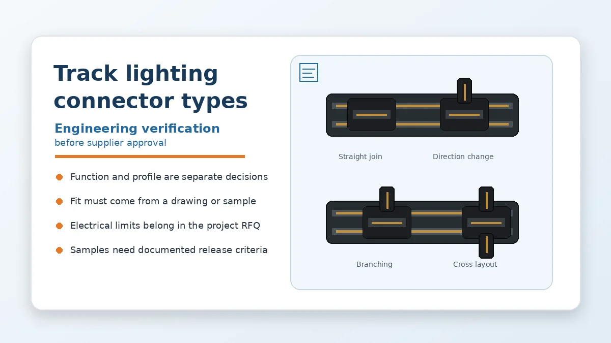
Procurement rule: do not approve a track connector from an H, J, L, single-circuit, or dual-circuit label alone. Request the track drawing, connector drawing, polarity information, and a representative sample when interchangeability is not already documented.
Separate Connector Function from Track Profile
Two naming systems are commonly mixed together. One describes function: live-end feed, straight join, directional connector, branch connector, flexible connector, or end termination. The other describes the physical track family. A correct functional type can still be mechanically wrong for the installed track.
Begin with the installation layout. Mark every point where power enters, track sections join, direction changes, or a run terminates. This establishes the connector function before any supplier comparison. Then match each position to the exact track cross-section, rail arrangement, keying features, and polarity shown in the project documentation.
A site photo can help identify the general family, but it cannot reliably show small interface differences. For legacy systems without drawings, the safer procurement action is to provide a physical track section and the mating part for measurement. Treat any proposed cross-reference as provisional until the mechanical interface has been checked.
Map Common Track Lighting Connector Types to Their Checks
The table below organizes connector types by the work they perform. It intentionally avoids claiming brand equivalence because letter-based naming and profile details can differ between systems.
| Connector function | Where it is used | Mechanical release check | Electrical and procurement check |
|---|---|---|---|
| Live-end or power-feed connector | Introduces the incoming supply to a track run | Confirm track profile, locking engagement, wire-entry space, and strain-relief arrangement | Confirm project current and voltage requirements, conductor range, polarity, and required test evidence |
| Straight joining connector | Connects two track sections in one line | Check rail alignment, insertion depth, joint gap, and whether the connector preserves orientation | Confirm continuity across the joint and whether the part is a mechanical join, an electrical join, or both |
| Directional connector | Changes the route of a track run | Verify left/right orientation where applicable, corner clearance, and polarity through the turn | Confirm that the selected orientation matches the reflected ceiling plan and installation sequence |
| Branch or cross connector | Creates multiple track directions from one junction | Check each branch profile, key direction, assembled envelope, and mounting clearance | Document the intended circuit routing; do not infer internal continuity from the external shape |
| Flexible connector | Bridges non-standard angles or offset track sections | Confirm allowable routing, bend condition, support method, and movement after installation | Ask whether repeated movement is expected and what sample validation is required for that condition |
| End or dead-end termination | Closes the end of a track run | Verify retention, exposed-interface protection, and end-of-run clearance | Confirm whether the item is only a cover or also includes an electrical function |
Common sourcing mistake: buying the right shape for the layout but the wrong profile for the track. The release decision should reference the drawing revision or the approved sample, not a catalog thumbnail.
Make Mechanical Compatibility the First Release Gate
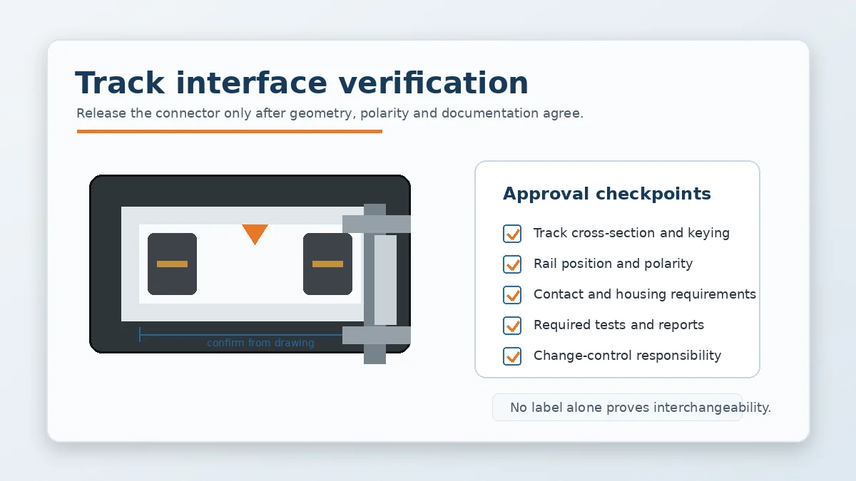
Mechanical fit is more than whether the connector can be pushed into the track. A part may enter the extrusion yet fail to place the contacts correctly, engage the lock fully, preserve polarity, or leave enough space for the planned cable and mounting method.
At minimum, compare the following items against the track drawing or measured sample:
- Cross-section and entry geometry: confirm the overall profile, internal ledges, and any asymmetrical features that control orientation.
- Rail and contact locations: verify that the contact points line up with the conductive rails and that the intended polarity is maintained.
- Keying and locking: check insertion direction, latch engagement, retention, and whether the connector can be installed incorrectly.
- Wire-entry and strain relief: confirm the cable approach, conductor preparation, enclosure space, and installation access.
- Assembled envelope: review clearances around ceilings, brackets, luminaires, covers, and adjacent track branches.
For a replacement project, include both the installed track sample and the original connector when possible. That lets the supplier compare the mating interface instead of working from a part number that may no longer identify the exact revision.
Put Electrical and Environmental Requirements in the RFQ
Once the interface is confirmed, the RFQ should state the conditions the connector must satisfy. Do not copy a current, voltage, temperature, material, plating, flame-rating, or environmental value from an unrelated product page. Those values should come from the customer drawing, the system specification, or supplier documentation approved for the project.
Useful RFQ questions include:
- What current, voltage, duty condition, and temperature-rise limit must be evaluated for the intended track arrangement?
- What insulation, creepage, clearance, housing material, terminal material, plating, and flame-rating requirements are specified?
- Will the connector be installed in a dry, damp, high-humidity, outdoor-adjacent, or frequently adjusted location?
- Are insertion and withdrawal force, retention, thermal cycling, hi-pot, insulation resistance, salt-spray, or other tests required by the project?
- Which reports must accompany samples and production lots, and which tests may be arranged through an external laboratory when needed?
This approach keeps uncertain data in the form of engineering questions until evidence is available. It also gives purchasing teams a clear basis for comparing quotations that may otherwise look similar.
Use a Project-Specific Sample Approval Plan
A catalog drawing is not the final approval record for a safety-relevant power interface. Before series supply, define a sample gate that reflects the actual track and installation. The required depth depends on the project, but the release package may include dimensional inspection, polarity and continuity checks, fit verification with the target extrusion, and the reports listed in the RFQ.
Where the application requires additional validation, state the test method, sample quantity, acceptance criteria, and responsible party before samples are built. This prevents a later disagreement over whether a generic supplier report is sufficient for the end product.
- Freeze the drawing revision and track sample used for comparison.
- Record critical dimensions and orientation features on the inspection plan.
- Confirm the electrical route and polarity in the assembled track.
- Review material and test documents against the RFQ, not against a generic checklist.
- Approve changes only through a documented engineering-change process.
Evaluate Supplier Capability Without Turning It into a Guarantee
Company materials available for this article list tooling, injection molding, stamping, assembly, and inspection-related process steps. They also describe project-dependent engineering support that may include Pro-E modeling, Moldflow analysis, ABAQUS terminal stress analysis, and SI simulation. These capabilities can support a review, but they do not by themselves prove that a specific track connector is compatible or approved.
Ask which steps are relevant to the quoted part. A catalog component may require only drawing review, sample inspection, and documentation. A modified housing or terminal may require tooling and process evaluation. A new design may need a broader DFM and validation plan. The supplier should state the actual scope instead of presenting every available capability as standard for every order.
For connector projects beyond track lighting, see LinkManu’s Power Connectors for DC and High-Current Interface Projects page. You can also review the broader product categories or use the contact page to discuss drawing review and RFQ preparation.
Compare Price Only After the Technical Category Is Clear
Price comparisons are misleading when quotations cover different connector categories. One supplier may be quoting a catalog part, another a modified component, and another a new-tooling project. Before comparing unit cost, separate tooling, sampling, testing, documentation, packaging, and change-control responsibilities.
A lower unit price does not compensate for an undefined interface or missing approval documents. Conversely, a higher quotation is not automatically better. The procurement decision should show which technical requirements are included, which remain open, and which costs depend on final drawings or test scope.
Next Steps Before Releasing a Track Connector
Confirm the connector function, track drawing, cross-section, rail and polarity layout, cable entry, current and voltage requirements, environment, material and plating call-outs, required tests, documentation package, and supplier process scope. Then approve a sample against a controlled drawing or a clearly identified physical reference. If any of those inputs are missing, keep the item at the RFQ or sample-review stage rather than treating the family name as proof of compatibility.
Frequently Asked Questions
What are the main track lighting connector types?
Common functions include live-end feeds, straight joins, directional connectors, branch or cross connectors, flexible connectors, and end terminations. Each still needs to match the specific track profile.
Are H, J, and L track connectors interchangeable?
Do not assume so. Letter labels are not enough to confirm cross-section, rail position, keying, or polarity. Check the drawing or an approved sample.
How should a legacy track connector be identified?
Start with the original drawing and BOM. When those are unavailable, provide a track section and the mating connector for dimensional and interface review.
What should be included in a track connector RFQ?
Send the track and connector drawings, BOM, polarity layout, electrical requirements, environment, required tests, documentation needs, sample quantity, and expected production scope.
Send Your Connector Requirement
Share the drawing, BOM, track sample details, application conditions, and required documentation. LinkManu can review the available information and clarify the next RFQ or sampling questions.

Technical content reviewed by LinkManu Engineering Team
Prepared by LinkManu Editorial Team for B2B connector engineers, sourcing teams, and product development projects.