
Engineering & Quality
High Bandwidth Connectors Selection Guide for Real Projects
High-speed connector selection should begin with the channel requirement, not a familiar connector outline. A part can fit the enclosure and still leave insufficient electrical margin once the board footprint, connector, cable, return path, and operating environment are considered together. This high bandwidth connectors selection guide turns the early discussion into a practical engineering and sourcing checklist.
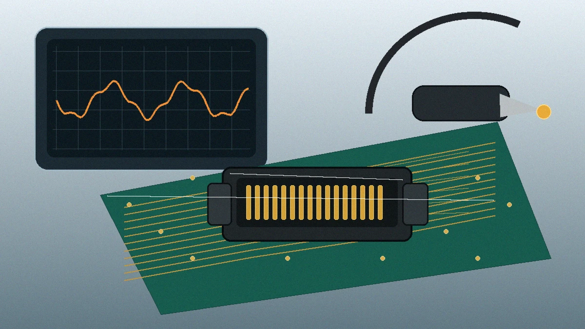
Selection rule: do not approve a connector from pitch, pin count, or a protocol label alone. Freeze the channel target, mechanical envelope, environment, and validation evidence before comparing quotations.
Start With the Channel Requirement, Not the Catalog
The first decision is whether the connector is being used as a short board-to-board transition, a pluggable external interface, or part of a cable assembly. Those paths expose the connector to different launch geometries, grounding arrangements, mechanical loads, and test boundaries. A supplier cannot assess the same drawing correctly if the intended signal path is missing.
Provide the protocol family and its revision, lane count, target lane rate, sideband contacts, channel length, and expected operating margin. Where the project references PCIe, SAS, Ethernet, or an SFF document, confirm the exact revision used by the system team. A family name is not evidence that a proposed connector and footprint meet the channel budget.
Warning signs that the current interconnect needs review
- Errors appear only at full traffic load, at temperature extremes, or after cable routing changes.
- Eye or channel measurements vary materially between samples or production lots.
- EMI troubleshooting repeatedly returns to the connector shield, ground path, or board launch.
- The mechanical drawing is approved, but no mated-pair or full-channel electrical evidence is available.
- A connector is being carried into a faster platform without a new validation plan.
None of these symptoms proves that the connector is the sole cause. They do justify separating the connector, footprint, cable, and board contributions before tooling or volume purchasing proceeds.
Freeze the Inputs That Control Connector Selection
A useful RFQ does more than request “a high-speed connector.” The table below identifies the project inputs that should be resolved or explicitly marked as open items. Missing values should remain questions; they should not be replaced with a supplier’s standard assumption.
| Requirement area | Information to confirm | Risk if left open |
|---|---|---|
| Signal path | Protocol revision, lane count, lane rate, channel length, and sideband contacts | The supplier may validate a different use case from the actual system. |
| Mechanical envelope | Connector family, pitch, pin count, mating height, keep-out area, and orientation | A late footprint or enclosure change can force a board revision. |
| Alignment and retention | PCB tolerance, blind-mating need, vibration, extraction method, and service access | Contact wear, incomplete mating, or solder-joint loading may be missed. |
| Environment | Temperature range, humidity, contamination, shock, vibration, and corrosive exposure | Bench performance may not represent installed conditions. |
| Validation evidence | Required models, S-parameters, reports, sample quantity, fixtures, and acceptance criteria | Quotations may look comparable while the evidence scope is not. |
| Production scope | Prototype timing, tooling ownership, traceability, inspection records, and change control | Commercial approval may occur before manufacturing controls are understood. |
Compare Connector Architectures by Their Constraints
Different high-bandwidth connector types solve different packaging and service problems. The correct category depends on the complete assembly, not on which option advertises the smallest footprint.
Pluggable I/O and cable interfaces
These interfaces suit removable cables or modules, but the review must include retention, shielding continuity, cable exit direction, strain relief, and the space needed to mate and unmate the assembly. In a dense chassis, a connector that fits the panel may still obstruct airflow or adjacent ports.
Board-to-board mezzanine connectors
Mezzanine systems can support dense parallel links between stacked boards. Confirm mating height, stack-up tolerance, alignment features, board stiffness, and the allowed assembly sequence. A low profile is not automatically safer when board bow or misalignment can load the contacts.
Custom cable assemblies
A custom assembly can address routing, bend radius, shielding, or ruggedization constraints. Its electrical review must cover the connector termination and cable as one assembly. Connector-only data cannot establish performance after termination, routing, and strain relief are added.
For the product-family context used in this review, see High-Speed Connectors for PCIe, SAS and Board-to-Board Signal Links.
Ask for Evidence That Matches the Proposed Build
Supplier evidence is useful only when its configuration matches the part being quoted. Request the connector revision, mated condition, board launch, cable construction where applicable, fixture method, and measurement boundary. A polished report from another pin count or footprint should be treated as background, not project acceptance evidence.
Engineering check: ask what differential environment the supplier evaluated, which PCB footprint was used, and whether the available data represents the connector alone or the complete mated channel. Do not copy a reference impedance or loss limit into the RFQ unless the system owner has approved it.
Depending on the project stage, the evidence package may include models, S-parameter files, simulation output, sample-run measurements, dimensional reports, and photographs of the test setup. LinkManu source materials describe engineering support that may include Pro-E modeling, Moldflow analysis, terminal stress analysis, and signal-integrity simulation. The applicable work should be confirmed for the specific product and RFQ scope rather than assumed for every project.
If a drawing references an SFF designation, verify the current document status through the SNIA SFF specifications list. Then state the exact document and revision in the RFQ. This avoids using a connector family label as a substitute for the required mechanical and electrical criteria.
Mechanical and Environmental Review Cannot Wait
High-speed electrical performance does not remove ordinary connector risks. The project still needs a defined ground path, contact protection, mating guidance, retention method, and assembly process. Blind mating, repeated service, vibration, or board-to-board misalignment may change which contact and housing design is acceptable.
- Shield and ground path: confirm how continuity is maintained through the mating interface and into the PCB or chassis.
- Alignment: check whether posts, guides, floating features, or the enclosure control mating position.
- Contact protection: review exposed-pin damage risk during assembly, transport, and field service.
- Qualification scope: identify which electrical, mechanical, and environmental tests are required and whether each test is performed in-house or arranged externally.
- Acceptance records: define the report, sample traceability, and pass/fail evidence needed before production approval.
Build an RFQ That Engineering and Procurement Can Compare
Quotations become difficult to compare when one supplier includes tooling, validation, and inspection while another quotes only the connector. Keep the commercial comparison tied to a shared technical package.
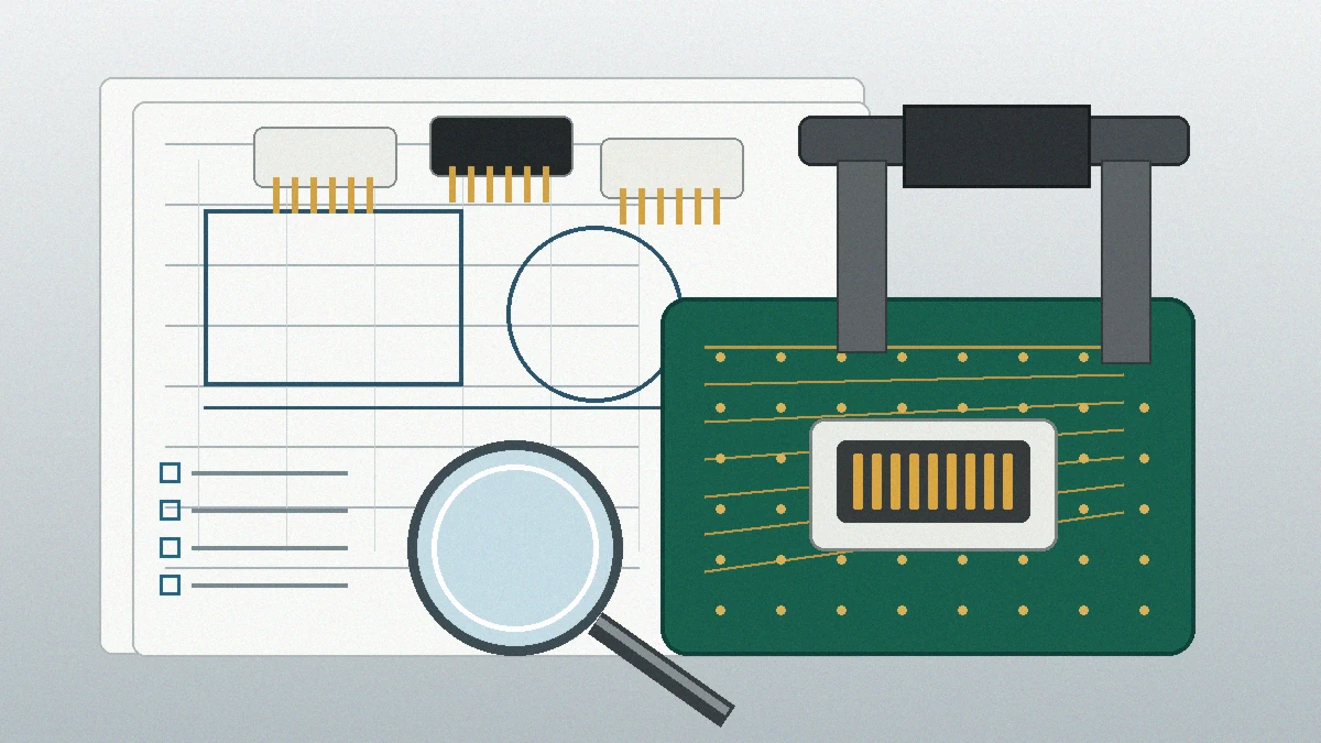
Include these items in the supplier package
- System block diagram and the connector’s position in the signal path.
- Mechanical drawing, PCB area, mating height, keep-outs, orientation, and enclosure constraints.
- Protocol revision, lane information, and approved electrical acceptance criteria.
- Operating environment and required qualification conditions.
- Requested models, reports, samples, test fixtures, and review milestones.
- Forecast, prototype quantity, target schedule, tooling expectations, and change-control requirements.
Questions for supplier capability review
- Which tooling, stamping, injection molding, assembly, and inspection steps are included for this product?
- Which validation activities can be completed before hard tooling, and what inputs are required?
- Which tests are available internally, and which must be arranged through an external laboratory?
- How are sample revisions, process changes, and inspection records linked to the approved drawing?
- What evidence will be delivered before prototype approval and before volume release?
A family-specific example is available in How to Choose the Right PCI-6513 High-Speed Connector for Your Application. Use it as a review example, not as proof that the same requirements apply to a different connector family.
Next Step: Complete the Requirement Sheet Before Shortlisting
Before requesting prices, confirm the drawing, connector family, pitch, pin count, mating height, lane requirements, environment, and validation documents. Mark unresolved items clearly. Then compare suppliers on the same sample plan, evidence package, manufacturing scope, and change-control expectations. That sequence exposes technical gaps before they become tooling, inventory, or board-revision costs.
FAQ: High-Bandwidth Connector Selection
What information should I send first?
Send the drawing, PCB or enclosure constraints, protocol revision, lane requirements, mating height, environment, and required validation evidence.
Is mechanical compatibility enough?
No. The connector, footprint, mating interface, cable or second board, and ground path must be reviewed as part of the intended channel.
How do I verify a supplier’s signal-integrity claim?
Ask for data tied to the quoted connector revision, footprint, mated condition, fixture, and measurement boundary. Confirm that the evidence matches your acceptance criteria.
Should I specify an industry standard in the RFQ?
Only when the system team has identified the exact document and revision. A standard family name alone is not a complete requirement.
Send Your Connector Requirement
Share your drawing, BOM, channel requirements, environment, and requested evidence. The project can then be reviewed for connector fit, sample scope, documentation needs, and RFQ readiness.