
Cable Assembly Engineering Guide
How to Review a Special-Purpose Connector Specification PDF for Cable Assemblies
A cable assembly special purpose electrical connector specifications pdf is useful only when the connector data is checked against the cable assembly that will actually be built. Before a buyer treats the PDF as an approved requirement, the connector revision, mating interface, termination method, cable construction, shielding, strain relief, routing, and test expectations still need to line up with the drawing, BOM, sample, and application.
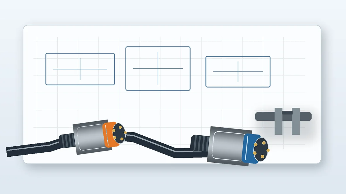
Practical rule: if a requirement cannot be traced to the current drawing, BOM, customer sample, approved datasheet, or test requirement, keep it as an open engineering question instead of turning it into a production assumption.
1. Start with the Connector PDF, but Do Not Stop There
A connector document can identify the family, mating face, contact arrangement, housing geometry, or termination concept. It does not by itself confirm that the selected part fits the cable construction, tooling, routing, overmold or strain-relief concept, or final inspection plan. That gap is where procurement and engineering reviews should concentrate.
Before sending a PDF to a supplier, confirm which revision is current and whether the project is buying an existing connector, adapting a known connector to a cable assembly, or reviewing a custom interface. A catalog image without a controlled drawing can leave keying, cable exit orientation, contact details, or mating requirements unresolved.
Checks to Make Before the PDF Becomes an RFQ Input
- Identity: connector family, drawing revision, pin count, keying, polarization, locking method, and mating part.
- Cable interface: cable specification, conductor size, insulation diameter, shielding, jacket, and exit direction.
- Termination: crimp, solder, IDC, screw terminal, or another specified process, plus the tooling or work instruction needed to execute it.
- Mechanical interface: strain relief, overmold interface, routing space, retention expectations, and any bend or exit constraints defined by the project.
- Application conditions: exposure, mechanical stress, material constraints, and any environmental requirement that must be verified from approved project documentation.
2. Separate Component Data from Assembly-Level Requirements
The same connector can create different assembly questions depending on how the cable is built. A shielded harness, an overmolded cable, or a cable with a constrained exit direction can change the termination and mechanical review even when the connector family is unchanged. The engineering decision is therefore not “Does the connector look correct?” but “Can the connector, cable, termination, and mechanical interface be controlled together?”
| Review area | What the PDF may show | What the cable assembly review must still confirm |
|---|---|---|
| Connector identity | Family, interface, contact arrangement, drawing references | Correct project revision, mating part, keying, polarization, and locking requirement |
| Termination | Contact or terminal concept | Wire and insulation fit, termination process, tooling, work instruction, and inspection method |
| Shielding | Shielded or unshielded connector options | How shield continuity is handled through the cable, connector, drain, shell, or panel interface |
| Mechanical fit | Housing dimensions and mating geometry | Cable exit direction, routing space, strain relief, overmold interface, and retention needs |
| Testing | Possible component-level test references | Which assembly-level checks are required by the customer drawing, sample, application, or test plan |
For cable assembly projects, the useful outcome of the PDF review is a list of confirmed requirements and open questions. LinkManu’s Custom Cable Assemblies & Wire Harnesses scope can be reviewed from drawings, connector selection, cable specification, length, shielding, and test requirements. The project record should show which of those inputs are confirmed before tooling or first-article decisions move forward.
3. Review the Connector Family in the Context of the Harness
Company materials list board-to-board, power, card edge, I/O, wire-to-board, wire harness, waterproof, and consumer electronics connector categories. That list is useful for scoping the conversation, but the category name is not a finished specification. Each family changes the questions that matter at the cable interface.
| Connector category | Engineering question to resolve in the RFQ |
|---|---|
| Board-to-board | Does the harness require a mating board transition, and which interface geometry is controlled by the drawing? |
| Power | Which conductor, retention, thermal, and test requirements must be confirmed for the end application? |
| Card edge | How are keying, mating depth, contact requirements, and the cable transition defined? |
| I/O | Does the assembly require shielding, panel grounding, locking, or controlled cable exit orientation? |
| Wire-to-board | Which termination method, cable construction, and strain-relief approach fit the assembly process? |
| Wire harness | Which connector, cable specification, wire size, length, shielding, and test requirements are controlled by the project documents? |
| Waterproof | Which sealing condition is actually required, and where is that requirement documented? |
| Consumer electronics connector | Which material, retention, packaging, and assembly constraints are defined by the product drawing or application? |
This is also why generic “electrical connector types” charts are a weak substitute for an RFQ package. They can help name a category, but they do not establish the project revision, termination feasibility, cable interface, tooling needs, or acceptance criteria.
4. Turn the PDF into an RFQ Package That Can Be Reviewed
A useful RFQ package lets the supplier identify missing information without guessing. Start with the connector drawing, then add the cable specification, BOM, sample or reference image if available, target application, and test requirements. If two documents conflict, flag the conflict explicitly instead of silently choosing one.
- Lock the document set. Identify the current connector drawing, cable drawing, BOM, and any sample or test report that should govern the review.
- Mark interface decisions. Confirm connector family, pin count, keying, polarization, locking, cable exit orientation, and shielding requirement.
- Mark process decisions. Confirm termination method, conductor and insulation fit, strain relief or overmold interface, and the tooling questions that remain open.
- List verification questions. Record which mechanical, electrical, environmental, or application-level checks the project requires without inserting unsupported values.
- Return the gaps before release. Use an engineering review to close drawing, BOM, sample, and documentation mismatches before the assembly is released for tooling or first article.
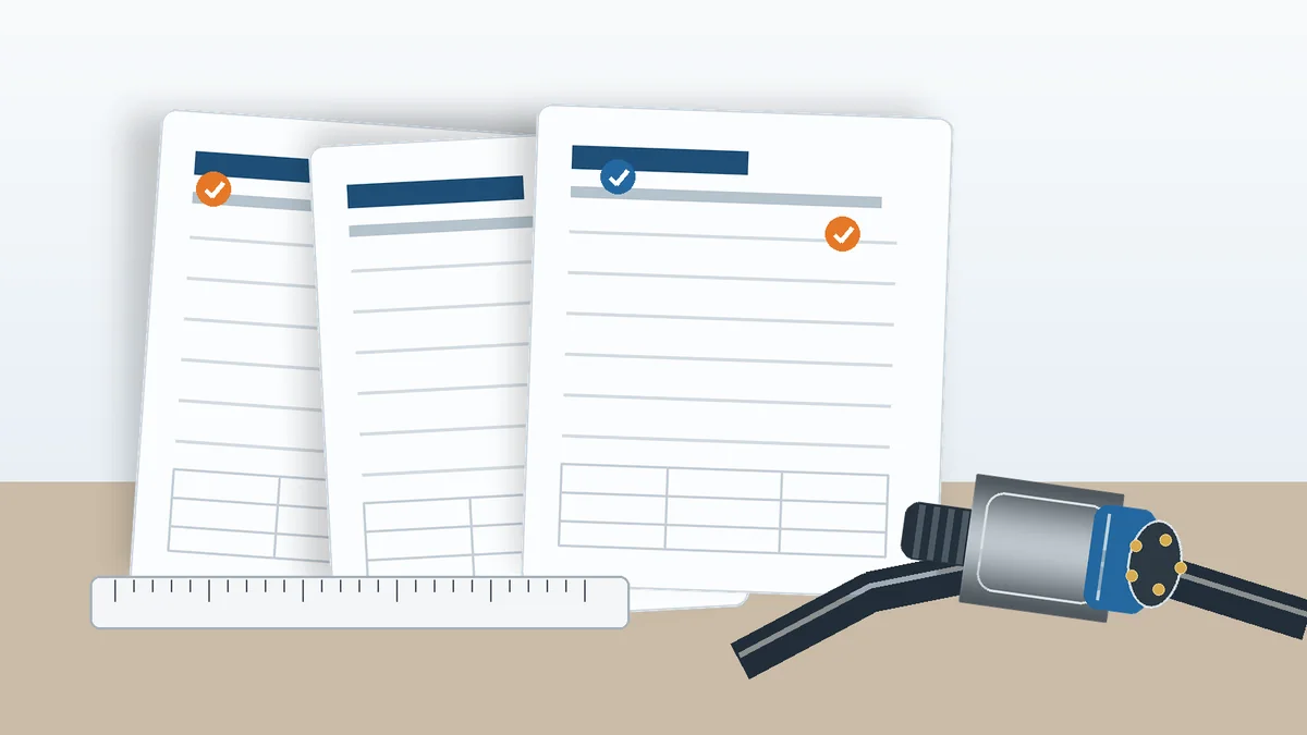
Documentation Checklist
| Input | What it should clarify | Review question |
|---|---|---|
| Connector drawing | Interface, revision, orientation, keying, and termination details | Is this the production revision and does it match the mating requirement? |
| Cable specification | Conductor, insulation, jacket, shielding, and length information | Does the cable construction fit the selected termination and mechanical interface? |
| BOM | Approved parts and mating components | Are part numbers, alternates, and revisions consistent with the drawings? |
| Sample or reference image | Physical fit, existing termination, strain relief, or overmold state | Does the physical sample agree with the released documentation? |
| Target application | Mechanical, environmental, material, and routing constraints | Which conditions must be converted into explicit drawing or test requirements? |
| Test requirements | What must be verified before approval | Which checks are mandatory, and which values still need an approved source? |
When the package is ready, Get Engineering Review can be used to submit the drawing and BOM context for project review.
5. Verify Supplier Capability Against the Actual Work Scope
A connector PDF also does not prove that the assembly process is available for the project. The RFQ should separate “connector exists” from “supplier can execute the required termination, molding, tooling, assembly, inspection, and documentation steps for this specific design.” That distinction is especially important when the project may need custom hardware or a connector-related tooling change.
Current company materials list assembly, injection molding, stamping, and tooling capabilities. They also describe design engineering, mold development, injection molding, post-processing, product assembly, and inspection before shipment as process steps that may apply depending on product type and RFQ scope. Project-dependent engineering support can include Pro-E modeling, Moldflow analysis, ABAQUS terminal stress analysis, and signal integrity simulation; those activities should be treated as scope items to confirm, not as automatic steps for every cable assembly.
For connector-related development context, see Custom Connectors. For a broader view of the available product categories, see Products.
Supplier-review question: which manufacturing and engineering steps are required by this RFQ, which are actually included in the proposed scope, and which external test or documentation items still need to be arranged?
6. Resolve Document Conflicts Before Tooling or First Article
If the connector datasheet, cable assembly drawing, BOM, and physical sample do not agree, do not assume one source is automatically correct. Record the conflicting fields, identify the controlled project revision, and obtain customer confirmation where needed. Typical conflict points include mating orientation, keying, wire or cable construction, termination method, shielding treatment, strain relief, and test expectations.
The same rule applies to replacement requests. A drawing review can compare the required interface and document the open compatibility questions, but compatibility should not be promised from a catalog description alone. The safer output is a confirmed requirement set, a list of remaining gaps, and a decision on whether the project needs an existing connector, an alternative part to be validated, or a redesigned interface.
Frequently Asked Questions
What should a cable assembly connector specification PDF include?
It should identify the connector and revision and give enough interface information to review termination, cable fit, shielding, mechanical retention, routing, and testing. If those items are not controlled in the PDF, they should be supplied through the drawing, BOM, cable specification, sample, or test plan.
What are the three or seven types of cable connectors?
A fixed count is not useful for an RFQ because connector categories can be grouped in different ways. For a cable assembly review, identify the actual connector family and then confirm the mating, termination, cable, shielding, mechanical, and test requirements that apply to that project.
Which connector standard should be used?
Do not choose a standard from the keyword or connector category alone. Confirm the applicable standard from the customer drawing, approved datasheet, sample documentation, test report, or end-application requirement before making a claim.
What are common electrical connector sizes?
There is no single size answer that is safe across connector families. Confirm the dimensions, contact arrangement, wire or cable fit, and mating interface from the controlled drawing for the specific connector series.
Can LinkManu review a connector PDF that conflicts with the cable assembly drawing?
Yes. The review can compare the documents and identify which interface, revision, termination, cable, and application questions still need confirmation. The review does not assume automatic compatibility or replacement equivalence.
Send Your Connector Requirement
Share the connector drawing, cable specification, BOM, target application, sample information, or test requirements that define the project. The review can focus on connector fit, documentation gaps, manufacturing scope, and RFQ readiness.

Technical content reviewed by LinkManu Engineering Team
Prepared by LinkManu Editorial Team for B2B connector engineers, sourcing teams, and product development projects.