
I/O Connector Engineering Guide
RJ45 Connector Pinout: I/O Connector Selection Guide
An RJ45-style connector can look familiar and still be wrong for a project if the pin assignment, PCB orientation, panel interface, or shielding path is assumed. For sourcing and design review, the useful question is not only “what is the RJ45 connector pinout?” but “which controlled pin map applies to this exact connector and assembly?” Start with the customer drawing, datasheet, sample, or approved test documentation before treating any generic wiring reference as the project requirement.
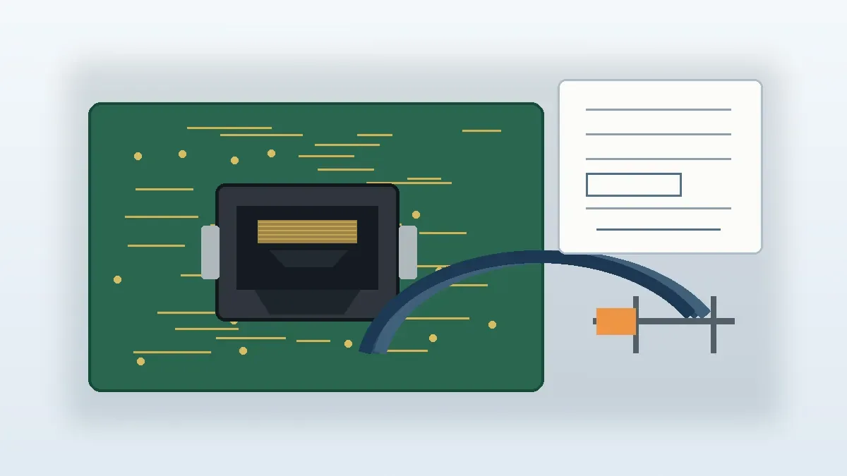
Start with the Controlled Pin Map, Not the Housing Shape
A BOM entry that says only “RJ45 connector” does not establish the electrical mapping or the mechanical interface. A standard-looking housing may still have project-specific signal assignments, a different board orientation, a different panel-mount arrangement, or a different grounding path. The procurement risk is approving a part that appears similar while the controlled drawing tells a different story.
Engineering decision: do not approve a connector from appearance or a generic color-code reference. Confirm the pin map and pin-1 orientation from the project-controlled source, then compare the mechanical and electrical interfaces against that same revision.
| Input to Review | Decision It Controls | Risk if It Is Missing |
|---|---|---|
| Pinout or signal map | Signal, power, and ground assignment | A connector can mate mechanically while the electrical mapping remains wrong. |
| PCB footprint and pin-1 reference | Pad or hole location, orientation, and board keep-out | Mirrored or rotated placement can survive schematic review and fail at assembly. |
| Panel drawing | Cutout, thickness, mounting direction, and flange space | The connector may fit the board but interfere with the enclosure. |
| Shielding and grounding requirement | Shell contact and grounding path | A mechanically acceptable part may not match the enclosure grounding scheme. |
| Application and test scope | Which mechanical, electrical, or environmental checks are required | The supplier cannot propose a meaningful qualification plan without the operating conditions. |
Review Pin Assignment and Mechanical Orientation Together
Pinout review should happen at the same time as footprint and panel review. A correct signal map on the wrong orientation is still a bad build input. The same applies to a panel connector whose cutout is correct but whose cable exit direction conflicts with the enclosure. These are interface decisions, not separate paperwork tasks.
- Identify the controlling document. Record the drawing or datasheet revision that defines the connector interface.
- Locate pin 1 and the mating view. Check whether the view is from the connector face, solder side, cable side, or PCB side before comparing pins.
- Confirm the signal-to-pin mapping. Mark any project-defined power, ground, or custom I/O assignments instead of assuming a default Ethernet mapping.
- Check the PCB relationship. Compare the footprint, mounting features, keep-out, component orientation, and cable exit direction against the board layout.
- Check the panel relationship. Confirm cutout geometry, panel thickness, retention, shield contact, and the available space around the connector.
- Flag open electrical requirements. Current, voltage, impedance, temperature, material, plating, flame rating, and test values should remain open until the project documents define them.
If the project uses a named wiring arrangement or installation standard, use the one specified in the customer-controlled engineering package. The connector shape by itself is not enough evidence to select a wiring arrangement, and a sourcing article should not replace the approved project drawing.
Three Mismatches to Resolve Before Sample Approval
- Drawing vs. schematic: make sure the schematic net names and the connector drawing describe the same pin references. If one document uses a functional label and the other uses only pin numbers, create a controlled cross-reference instead of interpreting the labels during assembly.
- Drawing vs. PCB footprint: compare the physical view direction, pin-1 marker, mounting features, and connector orientation. A footprint can look plausible on screen while being mirrored relative to the actual mating face.
- Drawing vs. harness or panel documentation: check which side of the interface each document shows and where the cable exits after installation. This catches cases where the electrical map is correct but the assembly direction, grounding path, or service access does not match the enclosure.
Do not close these mismatches by editing whichever document is easiest. Identify which source is controlled for the current revision, return conflicts to engineering, and record the approved resolution before samples become the de facto reference.
Turn the Pinout Question into an RFQ Package
A supplier can review an RJ45 connector package more effectively when the request separates known inputs from open questions. Do not hide missing data behind a generic part description. Mark the unknowns explicitly so engineering and purchasing can close them before sample approval.
| RFQ Item | What It Lets the Supplier Review | Preferred Source |
|---|---|---|
| Pinout drawing | Signal mapping, orientation, and project-specific assignments | Customer drawing or approved datasheet |
| PCB footprint | Pad or hole geometry, mounting relationship, and pin-1 reference | PCB layout or footprint drawing |
| Mechanical drawing | Panel cutout, retention, cable exit, and available envelope | Enclosure or assembly drawing |
| Application description | Environment, movement, moisture exposure, and shielding context | Project requirement |
| Test requirements | Which electrical, mechanical, or environmental checks must be planned | Qualification or acceptance plan |
| Target volume and sample need | Whether tooling, assembly, or sample planning needs early review | RFQ commercial input |
| Reference part or sample | Whether the project is evaluating a candidate alternative or a redesign | Customer-supplied reference |
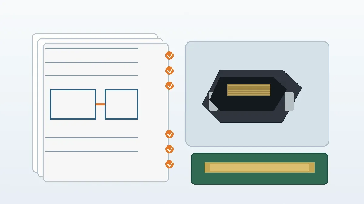
When the package is incomplete, use Contact Engineering Support to identify the missing drawing, sample, or test input before requesting a firm part decision. That is more useful than asking a supplier to infer the project from a short BOM description.
Use Samples to Close Fit and Documentation Risk
A drawing review confirms intent; a sample review checks whether the physical part matches that intent. Keep those stages separate. A sample should not be treated as proof that the drawing, pin assignment, PCB footprint, and panel interface are all correct unless those items are compared against the controlled documents.
A practical approval sequence is drawing review → sample request → first article inspection → functional test if required → documentation sign-off. Each stage should close a specific question. If a test is required, define it from the project scope rather than assuming a universal test plan for every RJ45-style I/O connector.
Supplier-scope check: current company materials support project-dependent review of I/O and rectangular connector requirements and list tooling, stamping, injection molding, and assembly capabilities. Engineering support may include Pro-E modeling, Moldflow analysis, terminal stress analysis, or SI simulation when relevant to the project. Not every connector or RFQ requires every process or analysis step, and some testing may be arranged externally when required.
Broader I/O connector projects can be reviewed in the context of I/O Connectors for External and Panel Interface Projects. Use that product-family context only after the project pinout, mounting relationship, and application requirements are clear enough to compare candidate connector packages.
Final Release Checklist for Engineering and Purchasing
- Controlled pinout or signal map is attached and the revision is identified.
- Pin-1 orientation and mating-view direction are unambiguous.
- PCB footprint and mounting orientation match the selected connector drawing.
- Panel cutout, retention, cable exit, shielding, and grounding requirements are documented where applicable.
- Project-specific electrical, material, environmental, and test requirements are confirmed or clearly marked as open.
- Sample approval criteria are tied to the drawing and BOM rather than visual similarity alone.
- Replacement or redesign intent is stated without assuming automatic compatibility.
- Tooling, stamping, molding, assembly, simulation, or testing needs are discussed only when the selected design and RFQ scope require them.
Before release, engineering and purchasing should be able to point to the same drawing revision, the same PCB orientation, the same signal map, and the same approval evidence. If any of those items are still uncertain, keep the connector decision open and close the missing document or test requirement first.
Frequently Asked Questions
What should engineers confirm for an RJ45 connector pinout?
Confirm the controlled signal map, pin-1 orientation, PCB footprint, mounting style, panel fit, shielding or grounding needs, and any project-defined power or custom I/O assignments.
Which RJ45 wiring standard should a project use?
Use the arrangement named in the customer drawing, installation specification, or other controlled project document. Do not choose one from connector appearance alone.
Can a generic RJ45 pinout table replace the connector drawing?
No. A reference table may help orientation, but the project drawing or approved datasheet should control the actual signal map, footprint, and mechanical interface.
What should be sent for supplier review?
Send the pinout drawing, PCB footprint, mechanical drawing, application conditions, test requirements, target volume, and any reference sample or part information available.
Send Your Connector Requirement
Share the controlled drawing, BOM, PCB footprint, target application, and open technical requirements. The review can then focus on fit, sample options, documentation gaps, and RFQ readiness without assuming unsupported parameters.

Technical content reviewed by LinkManu Engineering Team
Prepared by LinkManu Editorial Team for B2B connector engineers, sourcing teams, and product development projects.