
Board-to-Board Connector Selection Guide
FFC Connector Types for Board-to-Board Applications
Choosing among FFC connector types is not only a matter of finding the right pitch and pin count. In a board-to-board project, the connector must also fit the PCB stack, leave room for actuator operation, guide the flexible cable without excessive stress, and match the planned assembly and service process. A part that fits the footprint can still be unsuitable if the contact side, cable exit, or locking method conflicts with the mechanical design.
This guide focuses on the engineering and procurement decisions that should be completed before a connector is released to the BOM. It does not assign universal ratings to a connector type. Those values must come from the selected series drawing, customer requirements, samples, and project-specific documentation.
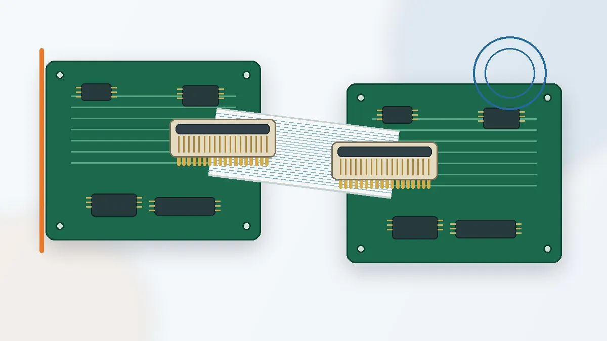
Start with the Interconnect Architecture, Not the Connector Name
An FFC link introduces compliance between two boards, which can help when a rigid direct-mating pair would make cable routing or assembly access difficult. That flexibility does not remove the need for a controlled stack-up. The cable still needs a defined entry direction, a suitable bend path, and enough clearance for the actuator to open and close without touching the enclosure or nearby components.
Before comparing series, define whether the two PCBs are parallel, offset, hinged, or assembled in separate steps. Then mark where the cable can move during installation. A connector placed near a board edge may simplify access, while the same connector placed under another PCB may be impossible to inspect after assembly. This is a layout decision, not a detail to solve after samples arrive.
First engineering decision: confirm the PCB stack-up, cable route, contact side, actuator access, and service method before freezing the connector footprint.
For projects that use a direct PCB-to-PCB interface rather than a flexible cable, review the broader board-to-board connector range. Keeping these architectures separate prevents an FFC connector from being selected merely because it appears compact in a catalog image.
FFC Connector Types That Affect Assembly
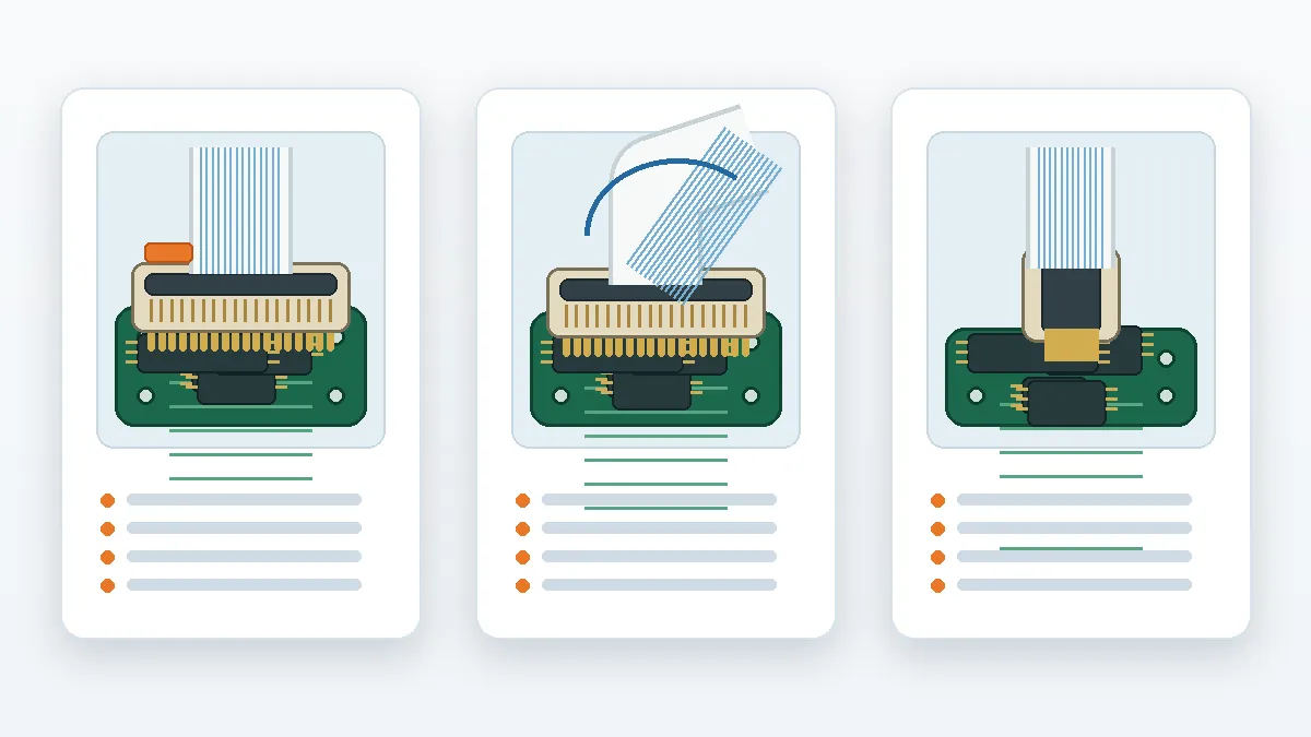
The useful classification is based on how the cable enters, which side of the cable carries the contacts, and how the connector retains it. Product naming varies by series, so the supplier drawing should remain the final reference.
| Connector Type | Assembly Characteristic | Where It May Fit | What Must Be Confirmed |
|---|---|---|---|
| ZIF, top-contact | A moving actuator locks the cable while the contact surface faces the specified side. | Horizontal cable entry where the actuator remains accessible from above. | Contact side, actuator opening envelope, insertion direction, and cable stiffener orientation. |
| ZIF, bottom-contact | The mating contact is on the opposite cable face from a top-contact version. | Layouts where cable routing or board placement requires the conductor side to face the PCB. | Drawing orientation; a mirrored footprint does not automatically create the correct contact arrangement. |
| LIF or non-ZIF | The cable is inserted without a separate locking actuator, depending on the series design. | Assemblies that favor a simpler insertion step and do not require frequent reconnection. | Retention method, insertion and extraction force, permitted service use, and cable thickness. |
| Vertical-entry | The cable enters approximately perpendicular to the PCB rather than along its surface. | Stacked or edge-constrained layouts where horizontal cable entry is blocked. | Top clearance, tooling access, bend location, and whether the cable can be inserted before the next assembly step. |
| Fixed or soldered cable termination | The cable is treated as a permanent interconnect rather than a field-removable connection. | Products where disconnection is not part of normal assembly or service. | Rework method, strain relief, cable replacement policy, and supplier process scope. |
A top-contact and bottom-contact connector can share similar external dimensions but still require different cable preparation and routing. Procurement should therefore avoid quoting only “FFC connector” plus a pin count. The RFQ should identify the required contact side, entry direction, actuator style, and the drawing revision used by the PCB team.
Mechanical Checks Before the Footprint Is Frozen
Contact side and cable orientation
Confirm which face of the FFC exposes the conductors at each end. A cable with contacts on the same side serves a different routing condition from one with contacts on opposite sides. The connector drawing, cable drawing, and PCB orientation should be reviewed in the same view. Otherwise, a correct footprint can still result in a cable that must be twisted.
Actuator access and keep-out space
The actuator needs room to open, close, and be inspected. Check nearby shields, housings, screws, heat sinks, and the second PCB in the stack. A tool-access path should also be defined if operators cannot reach the latch directly. Do not rely on the nominal connector height alone; the open-actuator envelope is the relevant constraint.
Cable bend and strain at the entry
Route the cable so that the first bend does not pull directly on the contact area. The required bend geometry depends on the cable construction and application, so the permitted condition should be confirmed from the cable specification or supplier review. Add a service loop only when the enclosure has room to control it; uncontrolled slack can interfere with adjacent components.
PCB stack-up and tolerance
Record board spacing, mounting hardware, board thickness, and positional tolerance. The flexible cable can accommodate routing differences, but the board-mounted connector should not be treated as a structural alignment feature. When the design specifically requires tolerance absorption at the mating interface, compare the FFC approach with floating board-to-board connector options and confirm feasibility from drawings and samples.
Assembly and service cycles
State whether the connection is mated only during factory assembly or opened during field service. The required durability cannot be inferred from “ZIF” or “non-ZIF” alone. Request the applicable series documentation and make the expected assembly sequence part of sample evaluation.
Electrical and Environmental Questions Belong in the RFQ
Mechanical fit is only the first gate. The selected connector and cable must also match the circuit and operating environment. The current files do not support publishing universal voltage, current, temperature, impedance, or life ratings for FFC connector types, so these values should be requested for the exact series under review.
- Signal assignment: provide the signal list and identify power, ground, and sensitive lines. Ask whether pin allocation or return-path planning needs additional review.
- Electrical ratings: confirm required current and voltage from the project specification, then request the relevant connector and cable documentation.
- High-speed performance: do not assume that a fine-pitch connector is suitable for a target interface. Provide stack-up and routing information when impedance or signal-integrity review is required.
- Operating environment: state temperature, humidity, vibration, contamination, and any other exposure defined by the end application. Required tests should be listed rather than implied.
- Materials and plating: identify any drawing-controlled housing, terminal, plating, or flammability requirement. Avoid substituting a generic material description for an approved specification.
Procurement risk: a quotation that omits cable thickness, contact side, pitch, pin count, and environment may identify a series that cannot be released against the final drawing.
When an FFC Interconnect May Not Be the Right Choice
An FFC connector should not be asked to solve every board-to-board problem. If the assembly requires the connector itself to locate two boards, a direct board-to-board family may be more appropriate. If board misalignment must be absorbed at the mating interface, a floating design deserves a separate review. If the connection will be opened frequently, actuator durability and handling controls become selection gates rather than secondary details.
High-speed or environmentally demanding projects also require series-specific evidence. A general type label does not prove impedance performance, retention under vibration, or suitability for a defined temperature range. The next action is to request the relevant drawing, test documentation, and sample—not to infer capability from a similar-looking connector.
Sample Review and Procurement Workflow
- Freeze the application inputs. Record PCB arrangement, cable route, contact side, required pitch, pin count, and assembly sequence.
- Request the latest drawing. Check footprint dimensions, cable dimensions, actuator operation, packaging, and revision status.
- Review the 3D fit. Place the model in the actual enclosure and verify keep-out space with the actuator open and closed.
- Build with representative samples. Use the intended cable and production mounting hardware rather than evaluating the connector alone.
- Apply the project test plan. Test only against documented requirements and record any supplier documentation still needed.
- Release the BOM with controlled references. Link the approved connector drawing, cable drawing, sample result, and supplier part identification to the purchasing record.
RFQ Information That Reduces Back-and-Forth
| RFQ Input | Why the Supplier Needs It | Recommended Evidence |
|---|---|---|
| Connector type and contact side | Separates top-contact, bottom-contact, vertical-entry, and other assembly conditions. | Marked PCB view or connector orientation sketch. |
| Pitch, pin count, and cable thickness | Narrows the series and checks compatibility between the connector and FFC. | PCB drawing and cable drawing. |
| Board stack and cable route | Allows review of actuator access, bend path, and surrounding keep-out areas. | 3D model, section view, or enclosure screenshot. |
| Electrical and environmental requirements | Identifies documentation and test questions that cannot be answered from connector geometry alone. | Project specification or requirement matrix. |
| Assembly volume and process | Supports packaging, handling, inspection, and sample planning. | Manual or automated process description and forecast range. |
| Required samples and documents | Clarifies what must be reviewed before BOM approval. | Sample quantity, drawing format, reports, and approval timeline. |
LinkManu connector projects can be discussed through the broader product overview, but final feasibility should be confirmed against the customer drawing, mating arrangement, cable details, application requirements, and requested documentation.
Frequently Asked Questions
What are the main FFC connector types?
Common selection categories include ZIF top-contact, ZIF bottom-contact, LIF or non-ZIF, and vertical-entry versions. Series drawings determine the exact configuration.
How do I choose between top-contact and bottom-contact?
Match the connector contact side to the exposed conductor face, cable route, and PCB orientation. Confirm all three on the drawing before releasing the footprint.
Is a ZIF connector always better for service access?
No. Review the actuator durability, handling method, access space, and permitted mating cycles for the exact series and service plan.
What should be sent with an FFC connector RFQ?
Send the PCB and cable drawings, pitch, pin count, contact side, stack-up, environment, electrical requirements, sample needs, and required documentation.
Send Your Connector Requirement
Share the drawing, PCB stack-up, cable details, application requirements, and documentation checklist. The review can then focus on connector fit, sample options, and unresolved RFQ questions.

Technical content reviewed by LinkManu Engineering Team
Prepared by LinkManu Editorial Team for B2B connector engineers, sourcing teams, and product development projects.