
RF Connector Engineering Guide
Types of RF Connectors for High-Speed Applications
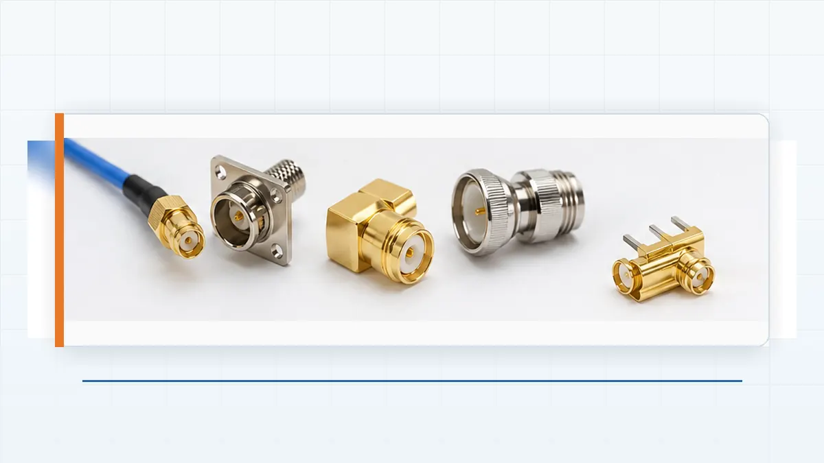
Selecting among the different types of RF connectors is not a catalog-only decision. A connector can mate correctly and still leave too little channel margin once the PCB launch, cable termination, enclosure, and real mating condition are included. Before a family is shortlisted, engineering and purchasing should agree on the signal interface, cable or board transition, available space, operating environment, mating cycles, and the evidence required for approval.
Why the Connector Family Is Only the First Decision
Names such as SMA, BNC, or MMCX identify a family, not a complete approved interface. Gender, polarity, mating style, cable termination, mounting method, and mechanical revision can change within the same family. The practical risk is a part that passes receiving inspection because the label looks correct but does not match the intended counterpart or channel construction.
Start the review with the customer drawing and the mating connector drawing side by side. Confirm the interface dimensions, mounting method, termination style, orientation, and the exact cable or PCB launch. Procurement should not release a purchase order from a family name or catalog photo alone.
Procurement gate: do not approve an RF connector until the drawing revision, mating counterpart, termination method, and required electrical evidence are linked to the same part number.
Compare Common Types of RF Connectors by Project Risk
The comparison below is a shortlisting tool, not a performance guarantee. Each row identifies the engineering question that should be resolved before the connector moves into sample validation.
| Connector family | Common mating style | Where it may be considered | Primary project risk | Required review item |
|---|---|---|---|---|
| SMA | Threaded | Modular RF boards, test connections, and compact coaxial paths | Assembly condition and the board or cable transition may dominate channel performance | Confirm the exact drawing, mating procedure, launch geometry, and supplier test evidence |
| SMB | Snap-on | Compact internal connections where quick mating is useful | Retention may be insufficient for the product vibration or cable-load condition | Verify retention force, cable strain relief, mating cycles, and enclosure support |
| BNC | Bayonet | Instrumentation, video, and accessible coaxial connections | Different interface variants can be confused, and the cable assembly may set the usable limit | Confirm the exact impedance version and review data for the finished cable assembly |
| N-Type | Threaded | Larger coaxial routes where mechanical robustness or environmental protection is needed | Envelope, sealing, thermal conditions, and installation practice may conflict with the enclosure | Check space, sealing construction, cable size, installation access, and environmental evidence |
| MCX / MMCX | Snap-on | Compact internal RF paths and board-level cable connections | Movement, rotation, and repeated mating can affect retention and contact condition | Review pull force, mating durability, cable routing, and support inside the enclosure |
| U.FL / IPEX-style | Push-on miniature interface | Board-to-antenna and other space-constrained internal links | Small mating features are sensitive to cable routing, handling, and available mated height | Confirm the approved counterpart, mated height, keep-out area, and cable retention method |
Evaluate the Complete Channel, Not Only the Connector Body
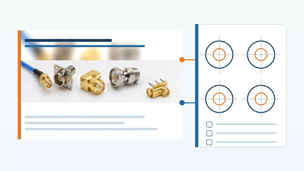
The connector body is only one discontinuity in the signal path. The PCB launch, via field, cable preparation, crimp or solder termination, and mating interface all contribute to the measured result. A supplier curve for the connector alone may not represent the production assembly that will be installed in the product.
Request S-parameter files, swept impedance or VSWR plots, or other channel evidence when those items are relevant to the project. The request should state what was measured: connector body, terminated cable assembly, board launch, or a complete representative channel. Engineering should also confirm the test fixture, sample configuration, and document revision before using the data for approval.
For board-to-board or direct-attach cable sections in the same system, review LinkManu’s high-speed connector range. This does not make an RF connector interchangeable with a board-level high-speed connector; it helps separate the coaxial interface decision from the adjacent board interconnect decision.
Drawing and sample checkpoints
- Match the connector part number to the approved mating interface, gender, polarity, and mounting orientation.
- Review the PCB footprint or cable termination drawing rather than relying on the connector outline alone.
- Confirm mated height, keep-out space, cable bend allowance, and access for assembly or service.
- Define retention, mating, or installation controls that apply to the final enclosure.
- Verify that materials, plating, and any flame-rating requirement come from the project drawing or approved specification.
- Record the sample lot, drawing revision, and test-document revision used for qualification.
The production BOM should not be frozen until the qualification sample and the proposed production part share the same controlled drawing and material definition.
Mechanical and Environmental Conditions Belong in the Selection
A connector that performs acceptably on an open bench may face a different risk inside the finished product. Cable load, vibration, humidity, contamination, temperature cycling, installation access, and repeated service can change the mating condition. The selection review should therefore use the product environment, not a generic connector-family description.
- Define whether the connection is internal, externally accessible, or exposed to moisture and contaminants.
- State the expected vibration or movement and identify whether positive locking or additional cable support is required.
- Confirm the number and purpose of mating cycles: assembly only, field service, or regular operator access.
- Separate assembly-process exposure from field operating conditions when reviewing materials and termination.
- Ask which environmental or mechanical tests are required and whether they are performed in-house or arranged through an external laboratory.
Do not infer protection from the series name. Sealing, UV resistance, temperature capability, and chemical compatibility must be confirmed for the exact connector construction and cable assembly.
Supplier Questions That Belong in the RFQ
A price request without drawings and acceptance criteria encourages assumptions. A stronger RFQ asks the supplier to identify what is confirmed, what still depends on the customer specification, and what must be validated on samples.
- Which exact connector and mating-part drawings are proposed, and what revision will control production?
- Can the supplier provide relevant impedance, insertion-loss, or VSWR evidence for the proposed production configuration?
- Does the evidence cover the connector body only, or the finished cable assembly and board transition?
- Which retention, mating-cycle, environmental, or electrical tests can be arranged for pre-production qualification?
- Which plastic, terminal, plating, and flame-rating requirements still need confirmation from the customer drawing?
- Which process steps—such as tooling, stamping, injection molding, assembly, and inspection—apply to this specific RFQ?
LinkManu can review a drawing, BOM, and application brief to determine whether the request fits the available connector and manufacturing scope. For a broader view of supported categories, see the LinkManu product range. The review should identify unsupported requirements early rather than convert them into an unverified capability claim.
A Practical Approval Sequence Before the Purchase Order
- Define the channel: document the signal interface, cable or PCB transition, environment, space, and service condition.
- Lock the interface: approve the connector and mating drawings, including orientation, termination, and mechanical envelope.
- Review evidence: identify which electrical and mechanical documents apply to the exact proposed configuration.
- Validate samples: test representative samples in the intended cable, board, and enclosure condition.
- Freeze the BOM: record the approved part number, drawing revision, materials, test records, and change-control requirements.
Price comparison is meaningful only after these items are aligned. Otherwise, quotations may describe parts that share a family name but do not represent the same engineering solution.
Next Step: Prepare the Drawing Package
Before contacting a supplier, collect the connector drawing, mating counterpart, cable or PCB launch information, available space, environment, required tests, sample quantity, and production forecast. Those inputs allow engineering to review interface fit and documentation gaps without guessing. Keep unconfirmed frequency, impedance, material, and durability values as RFQ questions until the exact part and evidence are available.
Frequently Asked Questions
What are common types of RF connectors?
Common families include SMA, SMB, BNC, N-Type, MCX, MMCX, and U.FL/IPEX-style connectors. The family name is only a starting point; the exact interface, termination, and application conditions still need confirmation.
How can RF connectors be grouped by mating method?
They are often grouped as threaded, snap-on or push-on, and bayonet interfaces. Specific families may include additional locking or polarity variants.
Does the connector series name confirm compatibility?
No. Confirm the mating drawings, gender, polarity, impedance version, termination, and mechanical revision before approval.
What should a buyer send with an RF connector RFQ?
Send the drawing, mating-part details, cable or PCB transition, environment, test requirements, sample quantity, and expected production volume.
Send Your Connector Requirement
Share the drawing, BOM, mating interface, application environment, and required documentation. LinkManu can review project fit, clarify missing inputs, and discuss sample or RFQ readiness.

Technical content reviewed by LinkManu Engineering Team
Prepared by LinkManu Editorial Team for B2B connector engineers, sourcing teams, and product development projects.