
I/O Connector Engineering
Non Standard USB Connector Selection for I/O Panels
A non standard usb connector should be considered only after the standard interface has been checked against the real panel, cable, and operating conditions. The protocol may be familiar, but the mechanical interface can become the weak point when a project needs positive retention, a defined panel seal, controlled keying, or a housing that must fit an existing enclosure.
Engineering judgment: do not start with “custom USB” as the requirement. Start with the failure condition or installation constraint that a standard connector cannot satisfy, then document that gap on the drawing and RFQ.
First Decide Whether a Non-Standard Interface Is Necessary
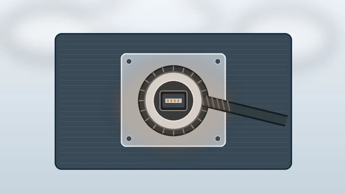
Many projects can stay with a standard connector when the port is protected inside the equipment, the cable is rarely disturbed, and the enclosure already provides the required environmental protection. Customization adds drawing control, supplier qualification, sample review, and possible tooling work. Those costs are difficult to justify when the only requirement is a different appearance.
A non standard usb connector becomes more reasonable when the interface must solve a specific mechanical problem. Typical review conditions include a cable that can be pulled during service, a panel opening that needs a defined sealing method, limited clearance behind the panel, a need to prevent accidental cross-mating, or an existing enclosure that cannot accept a catalogue footprint. The decision should be based on the installation, not on a general assumption that an industrial product always needs a ruggedized connector.
Before changing the connector envelope, compare the project with the available I/O connector families for external and panel interfaces. A standard I/O format may already address the retention or mounting problem without creating a fully custom part.
Convert the Operating Environment into Drawing Requirements
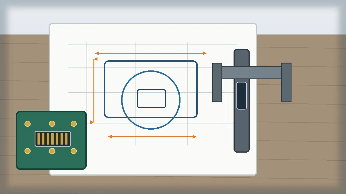
Terms such as “harsh environment,” “high reliability,” or “waterproof” are not sufficient for supplier review. They need to be converted into measurable acceptance items or, when values are not yet approved, clearly listed confirmation questions. The first drawing review should connect the panel cut-out, connector outline, PCB footprint, mounting hardware, cable exit, and mating direction into one tolerance chain.
Mechanical and Installation Checks
- Panel cut-out: confirm the shape, panel thickness, fastener positions, and installation side. A correct connector outline can still fail if the flange or nut cannot be assembled from the available side.
- Rear clearance: check the PCB location, board-to-panel distance, cable bend space, and nearby components. Do not approve a front view without reviewing the section view.
- Retention method: define whether the project needs a latch, threaded coupling, bayonet feature, screw lock, or another method. The required pull resistance must come from the application specification or test plan.
- Keying and orientation: document how the operator identifies the correct mating direction and whether similar ports are present on the same panel.
- Strain management: confirm whether the cable assembly, connector shell, or enclosure carries the service load. The PCB solder joints should not become the default strain-relief feature.
Environmental and Electrical Questions Before Tooling
| Requirement Area | What the RFQ Should Confirm | Risk if Left Open |
|---|---|---|
| Sealing | Where the seal is located, whether protection is required while mated or unmated, and which test document will define acceptance. | Supplier quotations may assume different gasket locations or no protection for the open receptacle. |
| Temperature and fluids | Operating and storage conditions, cleaning agents, oils, UV exposure, and the customer-approved material requirements. | A material selected from habit may not suit the actual chemical or thermal exposure. |
| Electrical path | Signal type, required data performance, current requirements, shielding approach, cable construction, and the validation method. | Mechanical fit may be approved before the electrical path has been verified. |
| Service life | Expected mating use, handling method, maintenance access, and the test evidence required by the project. | Different suppliers may quote different contact and plating systems without a common acceptance basis. |
| Compliance documentation | Which customer, market, or project documents apply and whether third-party testing must be arranged. | Certification scope can be assumed incorrectly or discovered after tooling begins. |
Control the RFQ So Suppliers Quote the Same Requirement
A BOM line that says only “USB connector” is too broad for a non-standard project. One supplier may quote a modified receptacle, another may assume a cable assembly, and a third may exclude the sealing or tooling work. The commercial comparison then looks competitive while the technical scope is different.
The RFQ package should identify whether the request is for a new design, a compatible alternative that still requires validation, or a redesign based on an existing sample. It should also state who controls the mating part, whether the PCB and panel can change, and which dimensions are critical to the equipment. A legacy part number can help identification, but it should not be treated as proof of drop-in compatibility.
Minimum RFQ Package
- Mechanical drawing or controlled sketch with panel cut-out, PCB footprint, mating direction, and critical dimensions.
- 3D model when surrounding clearance or enclosure interference is a concern.
- Electrical and cable requirements expressed as project targets or confirmation items.
- Environmental conditions and the required test or documentation plan.
- Expected sample quantity, production forecast, and the stage at which tooling approval will be released.
- Existing sample or mating component when the interface must be reviewed against legacy hardware.
Send the same revision-controlled package to every candidate supplier. If one quotation omits tooling, test fixtures, cable work, or documentation, record that exclusion before comparing price or lead time.
Evaluate Supplier Capability Against the Design Risk
Supplier capability matters because a non-standard connector may involve tooling, stamping, injection molding, assembly, and inspection. The current LinkManu fact set supports these manufacturing capabilities, but the exact process route depends on the connector design and RFQ scope. It should not be assumed that every project requires every process.
Engineering support described in the available company materials includes project-dependent use of Pro-E modeling, Moldflow analysis, terminal stress analysis, and signal-integrity simulation. These tools are most useful when they answer a defined risk: enclosure interference, molding feasibility, terminal deflection, or electrical-path validation. A long software list is not a substitute for an approved drawing and test plan.
Testing may include electrical, mechanical, or environmental checks, with outside laboratory support arranged when the project requires it. Procurement should ask which tests are proposed, who performs them, what sample stage is tested, and which document becomes the acceptance record. For a feasibility discussion based on a drawing or sample, use Contact Engineering Support.
| Review Item | Supplier Evidence to Request | Procurement Decision |
|---|---|---|
| Tooling control | Tooling responsibility, drawing ownership, change-control process, and maintenance scope. | Confirm who can correct dimensional problems after the first sample. |
| Manufacturing route | Which stamping, molding, assembly, and inspection steps apply to this specific design. | Do not accept a generic factory capability list as the project process plan. |
| Engineering review | Marked-up drawing, feasibility comments, simulation scope where needed, and open technical questions. | Release tooling only after critical interfaces and unresolved assumptions are visible. |
| Validation | Test matrix, sample stage, acceptance criteria, report format, and external-lab responsibility. | Confirm evidence requirements before the quotation is converted into a purchase order. |
| Change management | Material, process, tooling, and drawing change-notification method. | Protect the approved configuration after qualification and production release. |
LinkManu’s broader connector product range can be reviewed when the application may be better served by another standard or rectangular interface. The practical goal is not to maximize customization. It is to choose the smallest design change that resolves the documented mechanical, environmental, or sourcing constraint.
FAQ: Non-Standard USB Connector Projects
What makes a USB connector non-standard?
Its mechanical envelope, mounting, retention, sealing, keying, pin arrangement, or material system differs from a standard interface. The change must be controlled by a drawing and validation plan.
Are all USB connectors interchangeable?
No. Connector shape, mating interface, electrical implementation, mounting, and cable construction must all match. Similar appearance is not proof of compatibility.
Should I request a custom connector immediately?
No. First check whether a standard USB or another I/O connector solves the panel and retention requirement. Customization is justified when a documented constraint remains.
What should be sent with the RFQ?
Send the drawing, panel and PCB interfaces, cable details, environmental conditions, electrical targets, sample needs, and required validation documents.
Can an existing sample prove drop-in compatibility?
No. A sample helps identification and measurement, but compatibility still requires drawing, mating, electrical, and validation review.
Send Your Connector Requirement
Provide the drawing, panel cut-out, PCB interface, cable information, operating conditions, and required documentation. The first review should identify open assumptions before tooling or sample approval.

Technical content reviewed by LinkManu Engineering Team
Prepared by LinkManu Editorial Team for B2B connector engineers, sourcing teams, and product development projects.