
Automotive Connector Engineering
LV 214 Automotive Connector Standard Selection Guide
The LV 214 automotive connector standard is most useful when it changes the questions asked before a connector enters the BOM. A catalog description may identify a connector as sealed or suitable for vehicle use, but that description does not confirm that the selected configuration, harness routing, materials, and validation plan match the actual installation.
For engineers and technical buyers, the practical task is to connect application conditions to test evidence. Start with the vehicle zone, electrical load profile, mechanical constraints, exposure conditions, and required documentation. Then ask the supplier to show how the proposed connector and production process will be reviewed against those inputs.
Start With the Installation, Not the Catalog Label
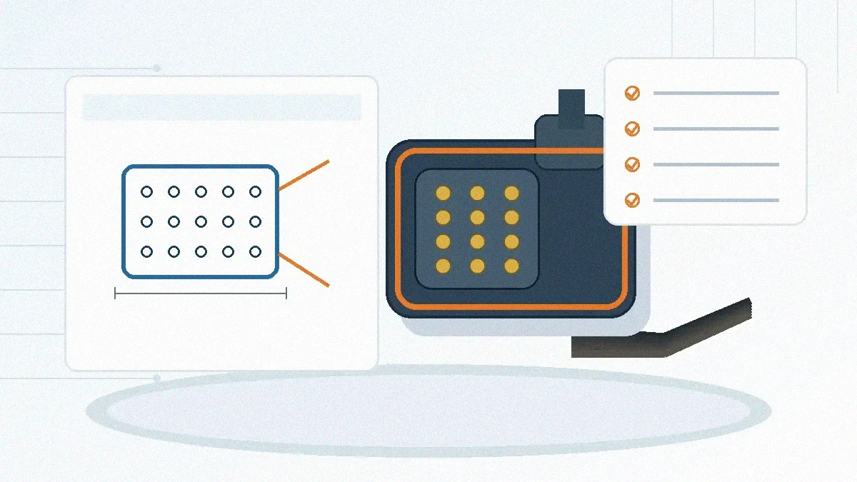
A connector cannot be selected from the standard name alone. The same family may be installed in a protected cabin module, near a moving harness branch, or in an exposed area where fluids and handling conditions differ. The engineering decision should therefore begin with the installation zone and the complete mated interface, not only the individual housing or terminal.
Before requesting samples, confirm the connector location, cable exit direction, available envelope, retention method, mating access, service procedure, and harness support. A connector that fits the PCB can still be a poor choice if the harness applies side load, the latch cannot be reached during assembly, or the mating direction conflicts with the enclosure.
Engineering check: Treat “sealed,” “automotive,” and similar catalog labels as screening terms. Request the applicable drawing, configuration-specific test evidence, and the supplier’s confirmation of what is covered—and what is not.
What the LV 214 Framework Changes in a Selection Review
LV 214 is a connector validation framework rather than a blanket approval for every part in a family. It organizes electrical, mechanical, environmental, handling, and aging checks so that the test plan can be matched to the intended application. The important procurement question is not simply whether a supplier has an LV 214 report. It is whether the report covers the proposed part number, materials, terminal system, sealing configuration, wire range, and required test path.
The Automotive Electronics Connector Solutions page provides the broader application context, but the final connector decision still depends on project-specific drawings and evidence. Use the following table to structure that review.
| Project input | Engineering judgment | Evidence or confirmation to request |
|---|---|---|
| Vehicle zone and environment | Exposure may differ across cabin, body, chassis, and other installation areas. | Required environmental class, exposure assumptions, and the test sequence that applies to the selected configuration. |
| Vibration and harness movement | Connector mass, cable support, routing, and mounting method can change mechanical load at the interface. | Mounting condition used for validation, harness support assumptions, and any limitations on routing or strain relief. |
| Electrical load profile | Terminal selection should be based on the real duty cycle and allowable temperature rise, not a single catalog number. | Part-specific derating information and confirmation against the customer load profile. |
| Mating and service conditions | Assembly access, repeated service, incomplete mating, and terminal damage can create risks outside normal bench testing. | Mating instructions, retention checks, inspection criteria, and the intended service condition. |
| Sealing configuration | Housing, seal, wire, cavity plugs, and assembly quality work as one system. | Configuration-specific sealing evidence and confirmation that the proposed wire and accessory set were included. |
| Documentation scope | A family-level statement may not cover the exact part number or revision being purchased. | Report revision, tested samples, deviations, change history, and traceability to the quoted part. |
Build the Evidence Package Before Design Freeze
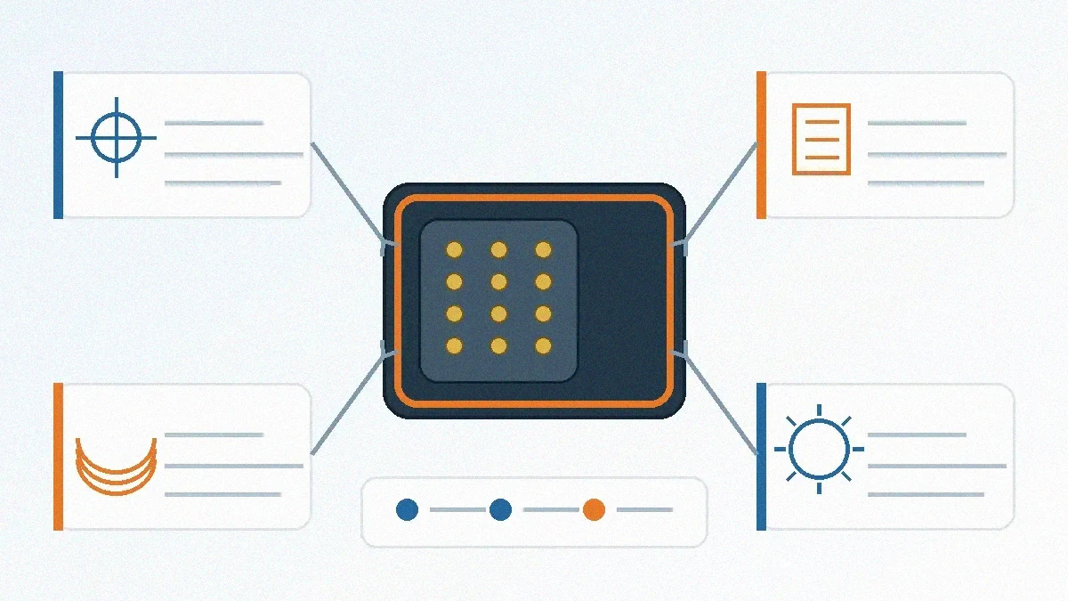
The safest point to resolve validation gaps is before tooling, harness drawings, and assembly instructions are locked. Once the connector is embedded in the enclosure and harness, even a small interface change can affect PCB layout, cable length, brackets, service access, and purchasing approvals.
A useful evidence package should identify the tested connector configuration and show how it relates to the quoted part. Depending on the project, request:
- A validation matrix or equivalent document showing the required checks and acceptance criteria.
- The exact part numbers, terminal system, housing, seals, accessories, wire conditions, and sample configuration used in testing.
- Electrical, mechanical, and environmental result summaries relevant to the application.
- Any deviations, excluded tests, conditional results, or outsourced test activities.
- Drawing revisions, material declarations, process controls, and change-notification expectations.
- A clear statement of whether the evidence is family-level, configuration-level, or part-number-specific.
Do not treat a test report as complete merely because it is long. The critical check is traceability: the report, drawing, sample, and quotation should describe the same configuration. If they do not, record the gap and assign an owner before the design review closes.
Review Supplier Capability Separately From Test Evidence
Passing evidence and repeatable production are related, but they are not the same question. A buyer should review how the supplier controls tooling, stamped parts, molded components, assembly, and inspection for the quoted connector. The required process depends on the product and RFQ scope, so the supplier should identify which steps are internal, which are outsourced, and how changes are controlled.
LinkManu’s Engineering & Quality information describes project-dependent support that may include Pro-E modeling, Moldflow analysis, terminal stress analysis, SI simulation, tooling, stamping, injection molding, assembly, and inspection. These capabilities should be matched to the actual project rather than assumed for every connector.
For a new or modified interface, use Custom Connector Support to review the drawing, manufacturability, tooling scope, sample plan, and documentation needs. The key procurement judgment is whether the proposed supplier process can hold the dimensions and assembly controls that the validated design depends on.
Supplier risk check: Ask how material, tooling, plating, assembly, and external test changes are approved and communicated. Validation evidence loses value when production changes are not linked to the reviewed configuration.
Do Not Assume One Automotive Standard Covers Another
Global vehicle programs may reference LV 214 alongside other customer or regional requirements. Do not assume that evidence prepared for one framework automatically satisfies another. Test sequences, sample definitions, documentation formats, and acceptance criteria can differ.
Ask the customer which specification and revision control the program. If more than one requirement applies, request a separate compliance matrix showing where evidence is shared and where additional testing or documentation is needed. This prevents a sourcing team from accepting a general “automotive qualified” statement that does not answer the program’s actual release criteria.
Prepare an RFQ That Can Be Reviewed Without Guesswork
- Attach the latest drawing. Include the connector interface, PCB or panel constraints, wire information, key dimensions, and revision status.
- Define the installation. State the vehicle zone, mounting method, harness support, exposure conditions, mating access, and service expectations.
- Provide the electrical duty. Share the load profile and ask the supplier to confirm the terminal and derating information for the proposed configuration.
- List required validation evidence. Identify the applicable standard, customer specification, report format, and any tests that require third-party support.
- Clarify samples and changes. State prototype quantity, sample approval steps, tooling status, expected revisions, and change-notification requirements.
- Separate facts from open questions. Mark unconfirmed pitch, mating height, material, plating, sealing, and test requirements as review items rather than assumed values.
Final Decision: Confirm the Configuration and the Evidence
The LV 214 automotive connector standard should lead to a documented selection decision, not a generic compliance claim. Before releasing the connector, confirm the drawing revision, interface dimensions, mating height, harness routing, electrical load profile, operating environment, validation matrix, report coverage, and supplier process scope.
When any of those inputs remain open, keep them visible in the RFQ and design-review record. LinkManu can review the submitted drawing, application conditions, sample needs, documentation scope, and supplier questions through the contact page.
Frequently Asked Questions
Does an LV 214 report approve every connector in a product family?
No. Confirm the tested part numbers, materials, terminals, seals, wire conditions, accessories, and report revision against the configuration you plan to buy.
Is a sealed catalog connector automatically suitable for an LV 214 project?
No. The complete mated system, installation, harness support, exposure conditions, and required validation evidence must be reviewed.
Can LV 214 evidence replace another customer or regional requirement?
Do not assume so. Ask for a requirement matrix that identifies shared evidence and any additional tests or documents.
What should be sent with an automotive connector RFQ?
Send the latest drawing, installation details, load profile, required validation documents, sample plan, and a list of unconfirmed parameters.
Send Your Connector Requirement
Share your drawing, BOM, application conditions, and documentation requirements for an engineering and RFQ readiness review.