
Engineering & Quality
What Do Terminal Blocks Do? Industrial Connector Functions Explained
Terminal blocks provide organized, insulated connection points for wires in control panels, machines, and device-level assemblies. In practical terms, what do terminal blocks do? They help engineers turn loose conductors into serviceable electrical nodes that can be assembled, checked, maintained, and modified with less wiring confusion.
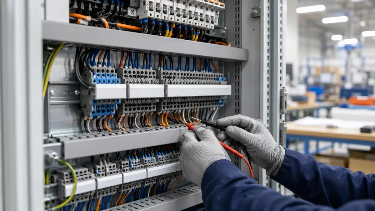
For LinkManu’s B2B connector customers, the topic is not only a basic electrical definition. It affects panel layout, maintenance access, wiring reliability, product qualification, and sourcing decisions. A terminal block can be a simple feed-through connection, a ground point, a pluggable board connector, or a functional interface that helps separate power, signal, and control wiring in a structured way.
What Is a Terminal Block in Electrical Design?
A terminal block is an insulated connector assembly that secures one or more conductors so current or signal can pass through a defined connection point. In electrical schematics, it often represents a boundary between field wiring and internal equipment wiring. In production, it becomes the place where a wire is inserted, clamped, labeled, inspected, and later serviced.
When engineers ask what is a terminal block, the useful answer depends on the application. In a control cabinet, it may be a modular row used for field I/O, motor control wiring, power distribution, and grounding. On a PCB, it may be a wire-to-board terminal block that lets a cable connect directly to the electronics. In a custom connector project, it may be one part of a larger interconnect system that must match the enclosure, harness, service method, and qualification plan.
Engineering note: A terminal block should not be selected by name alone. Confirm the termination method, conductor range, pitch, material, mounting style, environmental exposure, and applicable project documentation before release.
What Are Terminal Blocks Used For?
What are terminal blocks used for in industrial equipment? Their main role is to create repeatable connection points that reduce wiring disorder and make circuits easier to commission. Instead of splicing wires randomly or routing every field wire deep into a controller, engineers can terminate field wiring at an accessible block and route internal wiring from there.
Common use cases include connecting sensors to PLC inputs, distributing control voltage, joining neutral or ground paths, routing motor starter wiring, connecting cabinet wiring to a PCB, and creating testable points for troubleshooting. In each case, the value is not only electrical continuity. The value is also organization, labeling, replacement access, and inspection clarity.
Wire-to-Wire and Wire-to-Board Roles
- Wire-to-wire terminal blocks: Used inside panels or enclosures to join incoming and outgoing conductors in a controlled, accessible layout.
- Wire-to-board terminal blocks: Mounted to a PCB so external wires can connect to a power supply, controller, drive, sensor module, or embedded device.
- Pluggable terminal blocks: Used when the wired portion and electronic portion need to be separated during assembly or maintenance.
- Ground and protective connection blocks: Used to organize protective conductors and support a clearer grounding structure inside an enclosure.
Why Terminal Block Selection Matters
Every conductor termination is a potential weak point if the connector is poorly selected or assembled. Vibration, wire movement, heat, condensation, and installation variation can all affect a connection over time. A loose or inconsistent termination may cause intermittent sensor signals, unexpected equipment stops, visible heating, or difficult troubleshooting work.
This is why what do terminal blocks do is also a reliability question. A good terminal block selection gives the design team a defined way to clamp the conductor, route the wire, inspect the connection, and service the circuit later. A poor selection can create a hidden maintenance burden even if the product passes basic bench checks.
Typical Failure Modes to Review
- Loose conductors caused by incorrect installation method or vibration exposure.
- Wire fatigue where the conductor exits the block without adequate strain relief or routing space.
- Contact degradation caused by moisture, contamination, or mismatched conductor preparation.
- Overheating caused by using a terminal block outside the confirmed electrical or thermal design window.
- Assembly errors caused by unclear labeling, crowded wiring paths, or mixed connector types.
Four Connector Features Engineers Should Compare
For searchers asking what four connector features should be considered, terminal blocks can be evaluated through four practical groups: electrical fit, mechanical fit, termination method, and operating environment. These groups help convert a broad keyword such as what are terminal blocks into a usable engineering checklist.
| Feature Group | What to Compare | Why It Matters |
|---|---|---|
| Electrical fit | Rated current, rated voltage, conductor size, circuit function, and safety margin based on approved documentation. | Prevents using a block outside the confirmed design window. |
| Mechanical fit | Pitch, pole count, mounting style, enclosure clearance, wire entry direction, and service access. | Determines whether the block fits the cabinet, PCB, or device housing. |
| Termination method | Screw clamp, spring clamp, push-in, pluggable, or custom hybrid termination. | Affects assembly speed, maintenance routine, conductor preparation, and vibration behavior. |
| Operating environment | Temperature exposure, moisture, vibration, chemicals, dust, and required project validation. | Connects connector choice to the real machine environment rather than a catalog-only view. |
Specific values should come from the manufacturer datasheet, customer requirement, or approved project drawing. If a value is only seen in a general web article or competitor page, treat it as an engineering question rather than a claim for your own design.
Terminal Block Configurations and Application Mapping
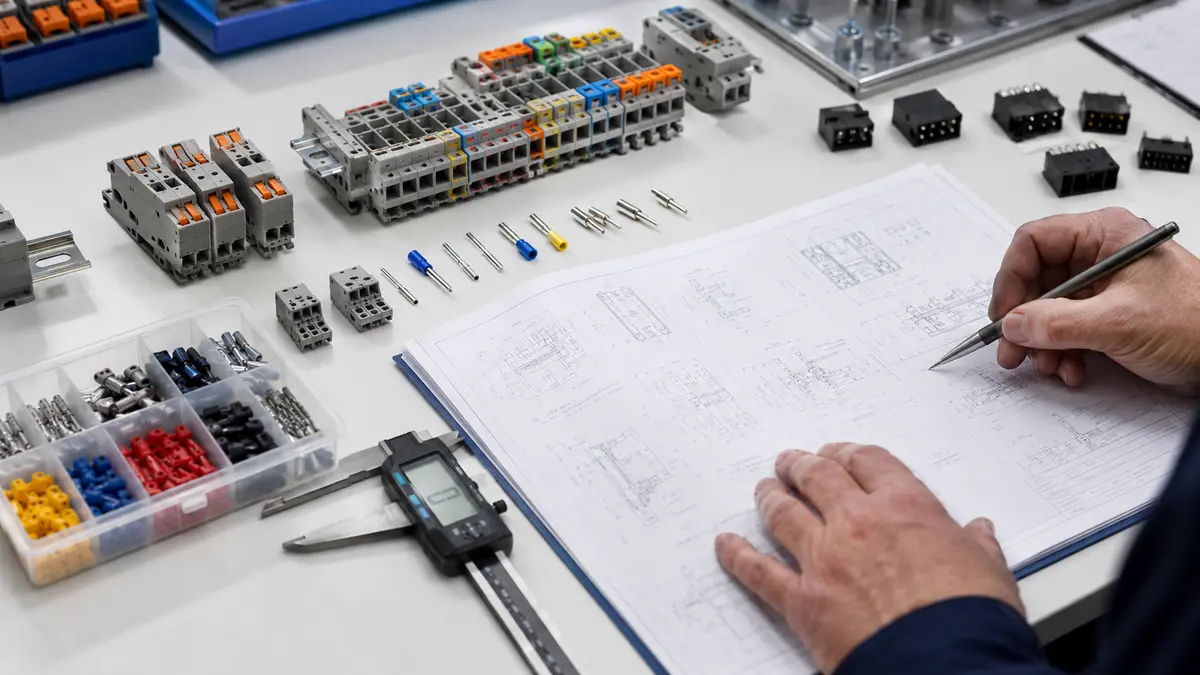
Different terminal block configurations solve different design problems. Feed-through blocks support general circuit routing. Multi-level blocks can help save panel space. Pluggable terminal blocks support faster device replacement or modular assembly. PCB terminal blocks connect external wiring to electronics. Grounding blocks and accessories help organize protective wiring paths.
| Application | Common Terminal Block Approach | Key Questions Before Selection |
|---|---|---|
| Industrial control panels | Feed-through, ground, multi-level, and pluggable blocks. | How will technicians label, inspect, and service the wiring? |
| PCB-based devices | Wire-to-board terminal blocks with through-hole or surface-mount designs. | Does the board layout support the conductor load, soldering process, and housing clearance? |
| Power distribution | Blocks selected for the confirmed circuit rating and heat management plan. | Are current, voltage, conductor size, and thermal rise confirmed by approved data? |
| Signal and sensor wiring | Compact blocks that keep signal routing organized and accessible. | How will shielding, wire routing, labeling, and test access be handled? |
| Custom equipment | Modified pitch, color, marking, housing, or hybrid termination options when standard parts do not fit. | Which constraints come from the enclosure, PCB, harness, compliance target, or assembly process? |
How LinkManu Reviews Terminal Block Requirements
LinkManu reviews terminal block and industrial connector requests from the standpoint of manufacturability, sourcing risk, and application fit. Our available factory capabilities include assembly, injection molding, stamping, and tooling, which supports discussion around customized housings, metal parts, and production-ready connector assemblies. Certification references include IATF 16949 and ISO 14001, so quality planning and documentation can be discussed during supplier qualification.
For machinery, automation, and equipment projects, terminal blocks often connect into a wider interconnect system. You can review related context on our Industrial Equipment Connector Solutions page, compare broader product families through View Connector Products, or use Engineering & Quality to understand the type of design and validation discussion that may be needed before production.
Procurement Questions to Clarify Early
- What conductor size, preparation method, and installation tool will production use?
- Does the design require wire-to-wire, wire-to-board, pluggable, or custom termination?
- What environmental factors should be considered during engineering review?
- Which drawings, BOM targets, inspection requirements, and customer standards must be matched?
- Will a standard part work, or does the project require custom housing, tooling, color, marking, or packaging?
When to Contact LinkManu
If your team is comparing terminal block options for a new control panel, PCB device, industrial machine, or custom connector assembly, share the drawing, BOM target, conductor requirements, and application environment. LinkManu can help evaluate whether a standard product family is suitable or whether a customized connector path should be reviewed.
For non-standard footprints, hybrid termination requirements, or production documentation needs, visit Custom Connector Support. For a confidential project discussion, use Contact LinkManu.
Frequently Asked Questions
What do terminal blocks do?
Terminal blocks secure wires at defined, insulated connection points. They help organize circuits, simplify inspection, support service access, and reduce wiring confusion in control panels, machinery, PCB devices, and industrial equipment.
What is the purpose of terminal blocks?
The purpose is to create repeatable connection points for wires. They make electrical systems easier to assemble, label, test, troubleshoot, and modify compared with unmanaged point-to-point wiring.
What is a terminal block in electrical work?
In electrical work, a terminal block is a connector used to terminate conductors and pass power or signal through a controlled interface. It may be used in cabinets, machines, PCB assemblies, power supplies, and automation devices.
What is the difference between terminal blocks and connectors?
Terminal blocks are usually fixed or semi-fixed wiring interfaces that clamp stripped conductors. Connectors often refer to mating plug-and-socket assemblies designed for repeated connection and disconnection. Some pluggable terminal blocks combine both ideas.
Can terminal blocks handle high-power circuits?
Some terminal block families are designed for power circuits, but the exact current, voltage, conductor size, temperature, and safety requirements must be confirmed from approved datasheets and project documentation before selection.
What information should I provide for a terminal block RFQ?
Provide drawings, conductor details, circuit function, mounting constraints, environmental conditions, target quantity, sample needs, and any required inspection or certification documentation. This helps the engineering team review fit before quoting.
Send Your Connector Requirement
Share your drawing, BOM target, application environment, or technical requirements. LinkManu can review connector fit, sample options, documentation needs, and RFQ readiness before final selection.

Prepared by LinkManu Editorial Team for B2B connector engineers, sourcing teams, and product development projects. Updated 2026.