
High-Speed Connector Selection
How to Select High Speed Multi Protocol Connectors for Your System Design
High speed multi protocol connectors selection should begin with the complete channel, not a connector catalogue. List the protocols, lane assignments, PCB stack-up, mechanical envelope, service conditions, and evidence required for approval. A connector may provide a suitable physical path, but protocol support still depends on the pinout, board routing, controller, and validation plan.
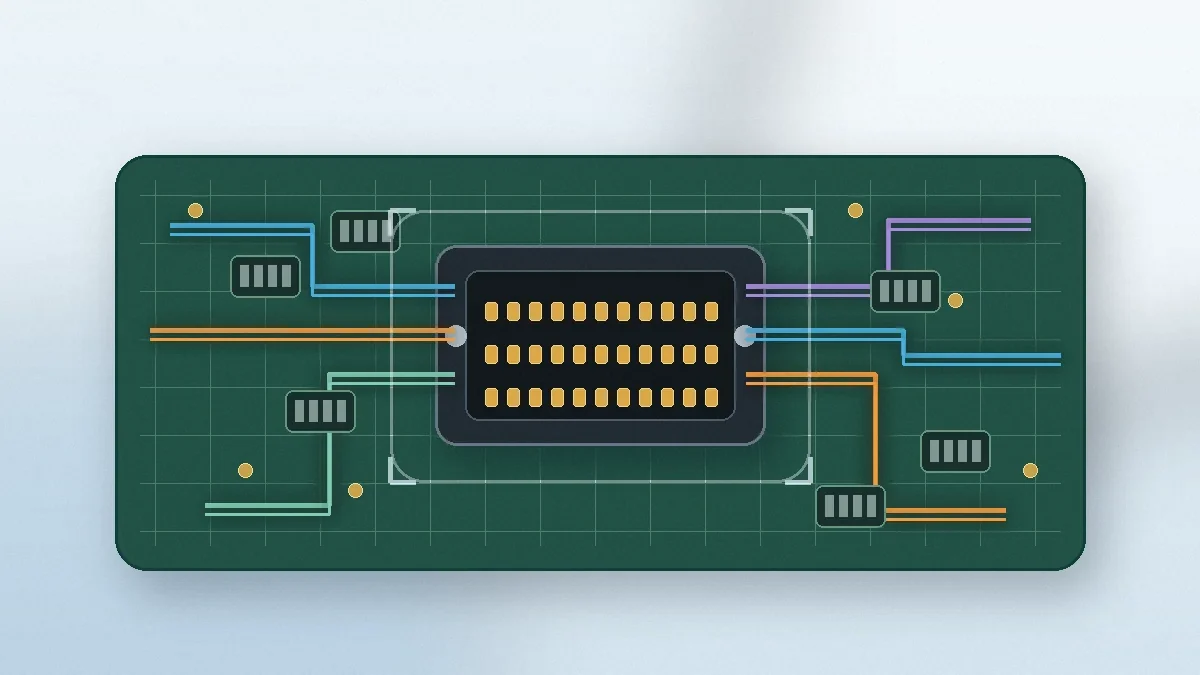
Start with the System, Not the Connector Family
A system carrying PCIe, SAS, Ethernet, or a proprietary serial interface does not automatically need a connector marketed as “multi-protocol.” The first decision is whether the same physical lanes will be reassigned between operating modes, used by different board variants, or populated differently across product configurations. That choice controls the pin map, ground allocation, keying, and validation scope.
Before comparing connector families, freeze the lane count, connector location, mating direction, board thickness, stack height, and keep-out zones. A mechanically convenient part can still be a poor choice when its breakout forces long stubs, weak return paths, or a footprint that conflicts with nearby components. The High-Speed Connectors for PCIe, SAS and Board-to-Board Signal Links page can be used as a product-family starting point, but final fit must be checked against the project drawing and channel requirements.
Selection gate: do not approve a connector only because one protocol is listed in a reference design. Confirm that the proposed pin assignment, ground pattern, PCB breakout, and validation evidence cover every operating mode planned for the product.
Map Protocol Requirements to One Physical Interface
“Multi-protocol” describes a system-level use case rather than a guarantee from the connector alone. Industry specifications may define connector, cage, module, cable, or form-factor interfaces, while the host design determines how lanes are routed and controlled. The applicable document and revision should be confirmed in the design record; the SNIA SFF specification directory is an allowed reference for checking document status.
| System Input | Engineering Decision | Risk if Left Open |
|---|---|---|
| Protocol list and lane ownership | Define whether lanes are dedicated, switched, or reassigned by product variant. | A late pin-map change can invalidate the footprint, grounding plan, or cable assignment. |
| Reference clock, sideband, and power pins | Separate high-speed pairs from control and power functions with an intentional return-path plan. | Shared or poorly placed returns can create coupling that was absent in a single-mode test. |
| Keying and mating control | Confirm whether mechanically similar variants must be prevented from mating. | A compatible outline does not prove electrical compatibility or safe field replacement. |
| Specification and revision | Record the exact interface document required by the customer or system architecture. | Using a family name without a revision can hide pinout or mechanical differences. |
Evaluate the Connector and PCB as One Channel
Connector performance cannot be separated from the launch region. Via structure, antipads, reference-plane transitions, trace geometry, and nearby aggressor lanes can consume more margin than the connector body. Supplier models are useful only when they represent the correct mating height, footprint, and breakout assumptions.
| Check | What to Review | Approval Evidence |
|---|---|---|
| Impedance continuity | Connector transition, pads, vias, plane changes, and the actual board stack-up. | TDR or an equivalent time-domain review on a representative coupon. |
| Crosstalk | Worst-case adjacent aggressors, ground placement, and lane reassignment scenarios. | Full-channel simulation or measurement with the relevant aggressor lanes active. |
| Insertion and return loss | Complete frequency range required by each planned operating mode. | S-parameter review tied to the project loss budget and fixture method. |
| Skew | Pair geometry, breakout length, connector orientation, and manufacturing tolerance. | Time-domain correlation on the same stack-up intended for the product. |
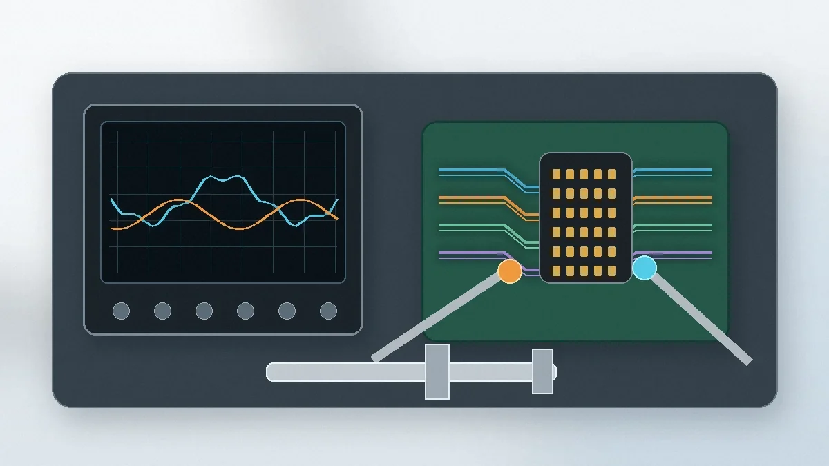
Mechanical and Environmental Constraints Can Override Signal Margin
A connector can pass an electrical review and still fail the project because the assembled geometry is unstable. Check mating height, alignment features, float, board warpage, latch load, and solder-joint stress using the actual enclosure and PCB tolerances. Field-serviceable connections also need a different mating-force and durability review from factory-installed interfaces.
- Mating condition: specify whether assembly is manual, automated, blind-mated, or serviced in the field. Request force and wipe information for the selected housing and board configuration.
- Durability: define the expected mate/unmate use and contamination conditions. Do not accept a cycle count unless its test conditions match the application.
- Temperature and current: review ambient temperature, contact loading, plating, and housing material together. Rated values from another configuration should not be transferred without confirmation.
- Environment: name the required humidity, vibration, corrosion, or other qualification evidence in the RFQ. The test plan should reflect the end use rather than a generic supplier report.
- Compliance: identify the exact quality-system, material, flammability, or process documentation required. Confirm the certificate scope and manufacturing site instead of assuming that a company-level certificate covers the requested part.
Turn the Selection into an RFQ-Ready Package
A useful RFQ lets engineering and sourcing review the same decision set. LinkManu project materials list capabilities including tooling, stamping, injection molding, assembly, Pro-E modelling, Moldflow analysis, terminal stress analysis, and SI simulation. Which steps apply must be confirmed for the connector family, drawing status, sample plan, and RFQ scope. The broader connector product families page can help identify the correct starting category before a detailed review.
| RFQ Item | Minimum Information | Decision It Supports |
|---|---|---|
| 2D and 3D drawings | Mating interface, tolerances, keep-outs, board edges, and enclosure limits. | Footprint fit, interference review, stack height, and alignment strategy. |
| Protocol and lane map | Every operating mode, lane ownership, sideband pins, and controller assumptions. | Pinout review and the scope of channel modelling or testing. |
| PCB information | Layer stack-up, breakout proposal, reference planes, and routing constraints. | Return-path continuity and launch feasibility. |
| Mechanical use | Mating method, expected service, retention method, vibration, and misalignment conditions. | Housing, contact, latch, and durability review. |
| Qualification evidence | Required electrical, mechanical, environmental, material, and compliance documents. | Sample plan, test responsibility, acceptance criteria, and supplier documentation. |
Final Selection Gate Before Samples
Do not release samples from a connector family name alone. Confirm the drawing, pin count, pitch, mating height, PCB footprint, lane map, current requirement, operating environment, test documentation, and supplier process scope. Any item that remains unknown should stay as an RFQ question rather than becoming an assumed product claim.
Frequently Asked Questions
What makes a connector multi-protocol?
The physical interface can be assigned to more than one protocol, but actual support depends on the specification, pinout, routing, controller, and validation results.
Can one connector carry PCIe, SAS, and Ethernet?
Potentially, when the interface and lane mapping allow it. Each planned mode still needs system-level channel and pinout validation.
What should be validated first?
Start with the lane map, PCB stack-up, connector footprint, ground returns, mating height, and the worst-case operating mode.
What should be included in the RFQ?
Provide drawings, protocol and lane requirements, PCB information, mechanical conditions, environment, sample quantity, and required test documents.
Send Your Connector Requirement
Share the drawing, lane map, PCB stack-up, mating height, operating environment, and required validation documents. These inputs allow the connector and test scope to be reviewed before sample selection.

Technical content reviewed by LinkManu Engineering Team
Prepared by LinkManu Editorial Team for B2B connector engineers, sourcing teams, and product development projects.