
Engineering Guide
How to Choose Electric Wire Connector Types for Wire-to-Board Designs
The most common types of electric wire connectors used in wire-to-board projects include screw terminal blocks, spring clamp or push-in connectors, insulation displacement connectors, and crimp-style housings with PCB headers. Each option solves a different assembly problem, so the right choice depends on wire type, board layout, service access, operating environment, and production workflow.
For engineers and sourcing teams, connector selection should happen before the PCB footprint, enclosure, and harness routing are frozen. A connector that looks acceptable in a catalog can still create problems if its termination method, latch structure, plating, or assembly process does not match the actual application.
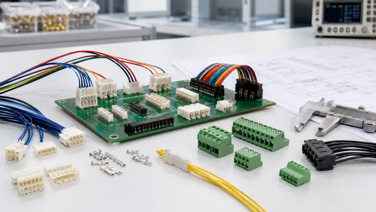
Why Wire-to-Board Connector Choice Matters
A wire-to-board interface joins flexible wiring or a cable harness to a rigid printed circuit board. That interface must carry power or signal while also tolerating handling, vibration, routing tension, and environmental exposure. Unlike a simple component choice, the connector affects PCB layout, harness drawings, crimp or insertion work instructions, inspection methods, and field service access.
Incorrect connector selection often shows up as intermittent faults rather than immediate open circuits. Common risk patterns include loose terminals, elevated contact resistance, damaged plastic housings, wire pullout, plating degradation, and assembly variation between operators. These issues are easier to prevent during design review than to correct after production tooling, board layout, and supplier sourcing are already locked.
Engineering note: Treat the connector as part of the electrical, mechanical, and manufacturing system. Ask for the applicable datasheet, drawing, recommended wire range, mating part information, and assembly guidance before approving a connector for production.
Main Types of Electric Wire Connectors for PCB Applications
The categories below describe general industry use. These types of electric wire connectors can look similar in a product photo, but their termination method and inspection requirements are very different. Exact ratings, dimensions, wire ranges, and materials must be confirmed against the specific connector series and part number.
Screw Terminal Blocks
Screw terminal blocks are often used where field wiring, maintenance access, or panel-style installation matters. A stripped conductor or ferruled wire is inserted into the terminal opening and secured by a screw-actuated clamp. Their main advantage is serviceability: technicians can loosen and reconnect wiring without specialized crimp tooling.
They are useful in control boards, industrial equipment, power supplies, and applications where visual inspection is helpful. The tradeoff is that torque control, wire preparation, and periodic service requirements should be considered. Dense PCB layouts may also need careful planning because terminal blocks can occupy more board area than compact crimp-style systems.
Spring Clamp and Push-In Connectors
Spring clamp and push-in connectors use spring force to hold the conductor. They can reduce assembly variation because the retention force does not depend on screw torque. These connectors are often considered for compact equipment, lighting controls, building automation devices, and other products where faster wiring can be valuable.
Selection still depends on the actual conductor. Solid wire, stranded wire, and ferruled wire can behave differently during insertion and removal. Engineers should verify the accepted wire type, release method, inspection method, and long-term retention under the expected vibration or handling conditions.
Insulation Displacement Connectors
Insulation displacement connectors, often called IDC connectors, create contact by pressing the wire into a terminal feature that displaces the insulation. This can support efficient termination for ribbon cable or multi-conductor signal wiring because several conductors can be terminated in one controlled operation.
IDC connectors are sensitive to wire construction and insulation characteristics. They should not be treated as universal replacements for stripped-wire or crimped terminals. Before using IDC in a PCB assembly, confirm the wire specification, termination tooling, strain relief, and mating header retention.
Crimp-Style Housings and PCB Headers
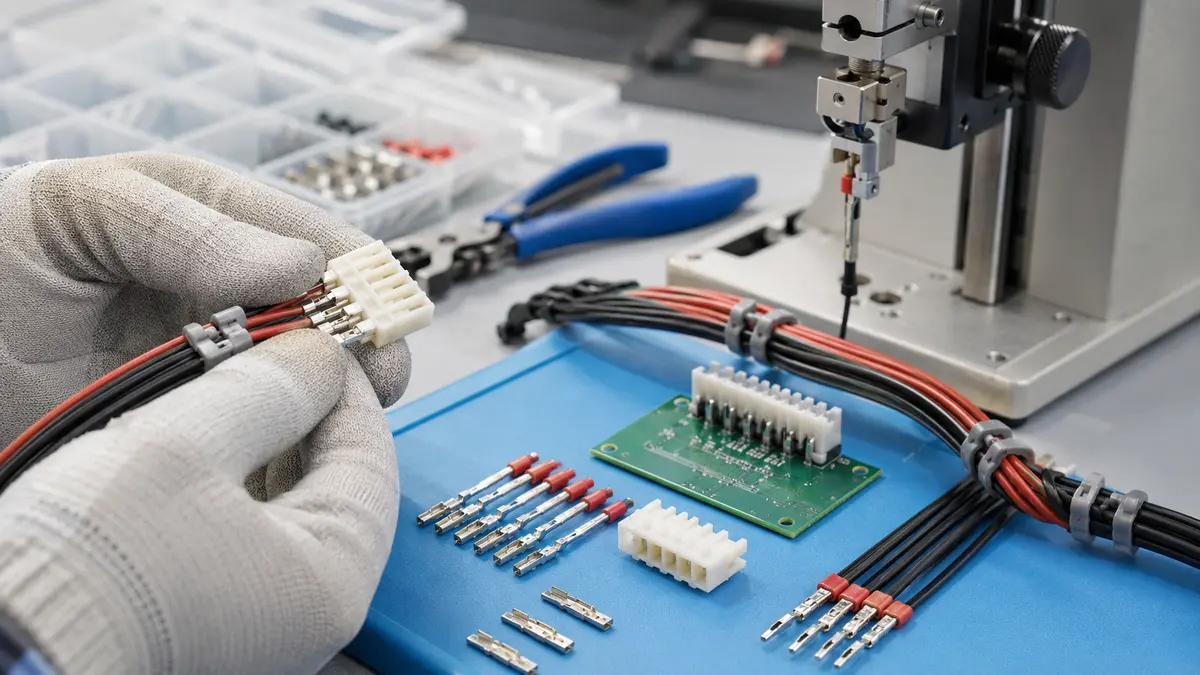
Crimp-style systems use a metal terminal crimped to a stripped wire, inserted into a plastic housing, and mated to a board-mounted header. This approach is common in harness-based products because it separates wire processing from final board assembly and can support structured inspection through crimp height checks, pull checks, terminal seating checks, and mating verification.
For production use, the quality of the crimp process is as important as the connector design. Tooling setup, terminal handling, wire strip quality, terminal retention, and operator training all influence final reliability. LinkManu documentation references in-house assembly, injection molding, stamping, and tooling capabilities, which can support project review when a standard or customized wire-to-board solution is being evaluated.
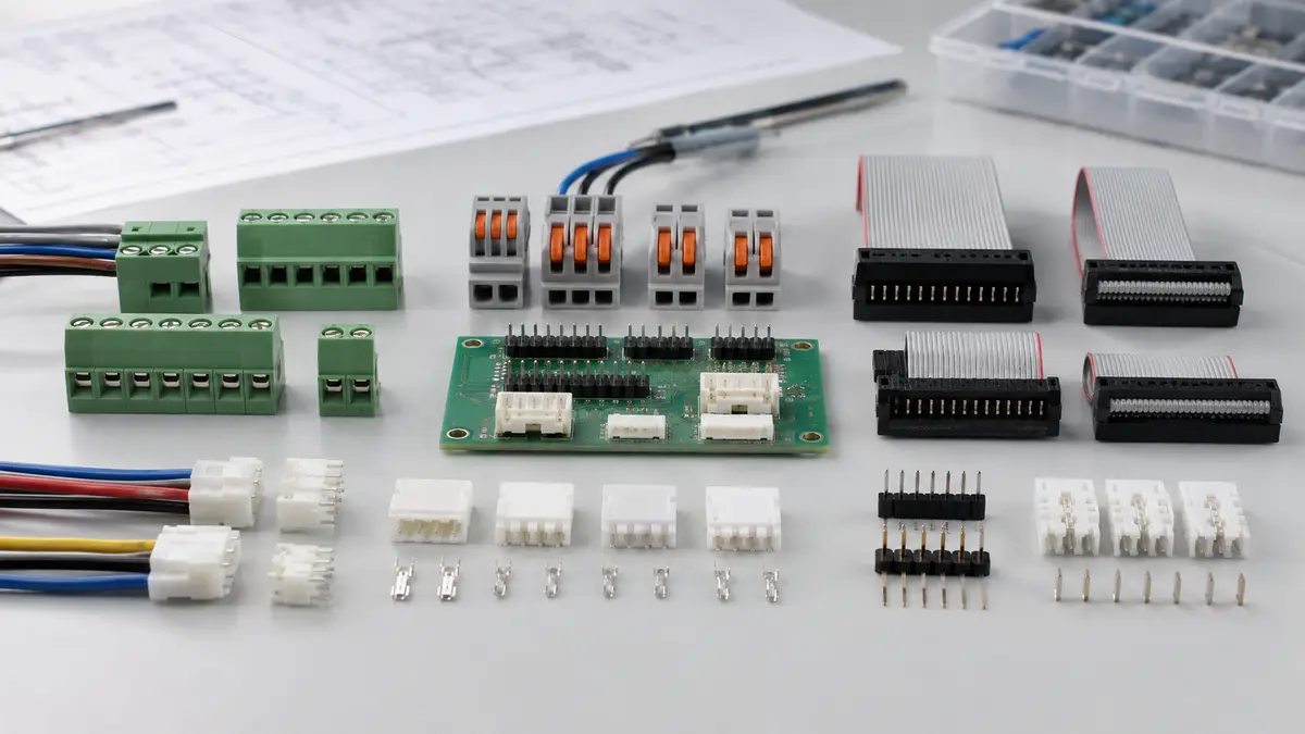
Comparison Table: Connector Types and Selection Tradeoffs
| Connector type | Typical use case | Termination method | Primary advantage | Design checks |
|---|---|---|---|---|
| Screw terminal block | Field wiring, control equipment, serviceable power or signal connections | Conductor secured by screw clamp | Easy field access and visual wiring inspection | Torque method, wire preparation, footprint, service plan |
| Spring clamp or push-in | Compact equipment, lighting controls, automation modules | Conductor held by spring force | Faster wiring and less dependence on screw torque | Wire type, release method, retention, vibration exposure |
| IDC | Ribbon cable, signal wiring, multi-conductor cable assemblies | Terminal displaces insulation to contact conductor | Efficient multi-wire termination | Wire and insulation compatibility, tooling, strain relief |
| Crimp housing and PCB header | Harness-to-PCB interfaces in production assemblies | Crimped terminal inserted into housing | Scalable harness process and compact PCB mating | Crimp tooling, terminal seating, latch design, mating part control |
Engineering Checks Before Selecting Wire-to-Board Connector Types
Wire Size and Conductor Construction
Start by matching the connector to the real conductor, not only to the schematic. Solid wire, stranded wire, fine-stranded wire, tinned wire, and ferruled wire can require different terminal geometry or insertion methods. The connector datasheet should state the supported wire range and conductor type. If the assembly uses multiple wire sizes in one harness, verify every circuit rather than assuming one connector family covers all positions.
Electrical Load and Derating
Current and voltage ratings should be reviewed as application-specific questions. Engineers should check steady load, peak load, ambient temperature, number of loaded circuits, creepage and clearance needs, and contact resistance stability over the product life. When comparing wire to board connector types, avoid using a general catalog rating as the only approval basis for a production design.
Mechanical Retention and Strain Relief
Wire-to-board connectors near fans, motors, moving panels, or frequently serviced areas need special attention to retention and harness routing. Positive latch features, terminal locking, cable tie points, service loops, and strain relief can reduce direct stress on the terminal interface. These features should be reviewed together with enclosure space and assembly access.
Environment and Materials
Humidity, dust, temperature cycling, cleaning chemicals, and vibration can all affect connector performance. Material and plating choices should be confirmed with the supplier for the target environment. For projects that need documented quality systems, LinkManu documentation references IATF 16949 and ISO 14001; buyers should request current certification documents and confirm the manufacturing site relevant to the quoted product.
For a related product-family overview, see LinkManu’s Wire-to-Board Connectors for PCB-to-Wire Interfaces page. You can also review the broader Products portfolio when comparing connector families across a design.
How to Insert Wire Into Terminal Block Connectors
The exact method depends on the connector series, but the process should be documented in the assembly work instruction. A practical review sequence is:
- Confirm the connector part number, wire size, conductor type, and drawing revision before preparing the wire.
- Strip the conductor according to the connector manufacturer’s datasheet, and inspect for damaged or missing strands.
- Use a ferrule only when it is compatible with the selected terminal and approved by the project specification.
- Insert the conductor fully into the terminal opening or clamp area according to the supplier’s application guidance.
- For screw terminals, use the specified torque method from the connector documentation.
- For spring or push-in terminals, verify the release button or tool access and confirm the wire is seated.
- Apply the agreed inspection method, such as visual seating review, continuity check, or sample pull check.
Procurement Questions to Clarify Before RFQ
Technical buyers can reduce back-and-forth by preparing the connector requirements before requesting samples or a quote. Useful inputs include:
- PCB layout constraints, target pitch, available height, and preferred mounting direction.
- Wire size, conductor type, insulation material, harness length, and routing limitations.
- Operating current, voltage, environment, service access, and mating cycle expectations.
- Preferred termination process, inspection method, and production volume range.
- Need for standard parts, semi-custom housing features, special color, packaging, or documentation support.
If you are unsure which types of wire connectors terminals fit your design, Contact Engineering Support with the drawing, bill of materials, or sample photo. The review can focus on connector fit, manufacturability, and the documentation needed for a reliable quote. This is especially useful when several types of electric wire connectors could satisfy the same schematic connection but require different assembly controls.
FAQ
What are the different types of electrical wire connectors used in PCB assemblies?
For wire-to-board PCB assemblies, the main categories are screw terminal blocks, spring clamp or push-in connectors, IDC connectors, and crimp-style housings with PCB headers. The correct option depends on wire type, service access, PCB space, and production process.
What are common electrical termination methods?
Common termination methods include screw clamping, spring clamping, push-in termination, insulation displacement, crimping, and soldering. For production designs, each method should be checked against the wire specification, tooling, inspection plan, and operating environment.
What are examples of cable connector styles?
Examples include terminal blocks, crimp housings, IDC ribbon cable connectors, circular connectors, modular connectors, D-sub connectors, and PCB headers. Not all are wire-to-board solutions, so engineers should first define whether the interface is wire-to-board, wire-to-wire, or board-to-board.
When should I contact a connector supplier during design?
Contact a supplier before the PCB footprint and harness drawing are finalized. Early review can help confirm mating parts, wire compatibility, termination process, and sample feasibility before the design becomes difficult to change.
Send Your Connector Requirement
Share your drawing, BOM, target application, wire details, and electrical or mechanical constraints. LinkManu can review the applicable wire-to-board connector options and clarify the documentation needed for samples or quotation.

Technical content reviewed by LinkManu Engineering Team
Prepared by LinkManu Editorial Team for B2B connector engineers, sourcing teams, and product development projects. Updated 2026.