
I/O Connector Selection Guide
SMA Connector Dimensions for I/O Connector Design
SMA connector dimensions matter because the connector is both a mechanical interface and an RF transition. In an I/O panel, the same part must match the PCB footprint, enclosure cutout, mounting hardware, cable exit direction, and electrical performance target. A mismatch in any of those areas can delay prototype review, complicate sourcing, or create avoidable fit questions during assembly.
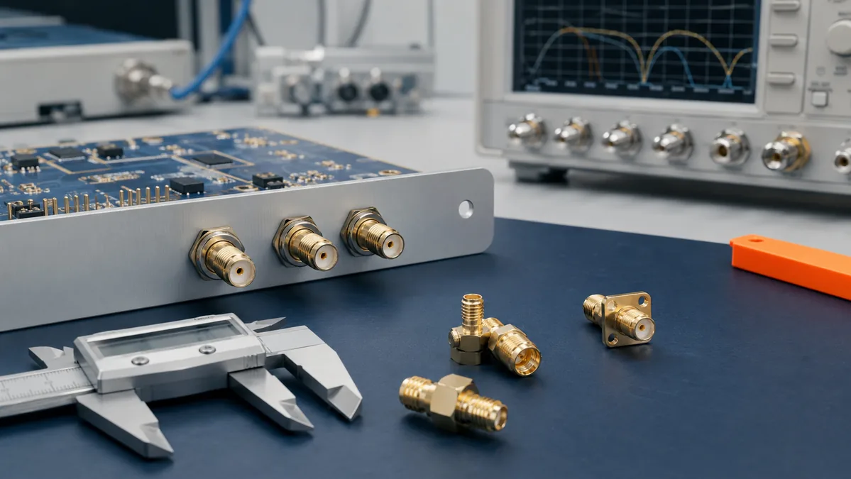
This guide focuses on how engineering and sourcing teams should review SMA connector size details before approving a part number. It avoids treating generic online dimensions as universal rules, because final values must come from the selected manufacturer drawing, datasheet, and project specification.
Engineering note: Any impedance, frequency, thread, pin, panel-hole, or footprint value should be confirmed against the exact connector series and revision. Use this article as a review framework, not as a substitute for a controlled drawing.
Why SMA Connector Dimensions Affect I/O Performance
An SMA connector is not only a small metal part on the edge of a product. It is part of the transmission path. The inner contact, dielectric support, outer conductor, mating face, and termination geometry work together, so mechanical variation can become an electrical discontinuity. In panel-mount and board-edge applications, that discontinuity may show up as poor return loss, unstable test results, or inconsistent cable mating.
Mechanical fit also affects reliability. If the connector shoulder does not seat cleanly against the panel, if the nut cannot engage correctly, or if the PCB footprint pushes the connector out of alignment, the assembly may pass an early visual check but still create stress at the solder joint or cable interface. That is why SMA connector dimensions should be reviewed before PCB release and enclosure machining, not only during incoming inspection.
Common Symptoms of Dimensional Mismatch
- Connector bodies do not sit flush against the panel or enclosure surface.
- Cable mating requires more force than expected or feels inconsistent between units.
- Board-edge connectors do not align with the plated pads or ground reference area.
- Panel holes, flats, washers, or nuts do not match the selected mounting style.
- RF test results vary after vibration, thermal cycling, or repeated mating.
Dimensions to Confirm Before PCB and Panel Release
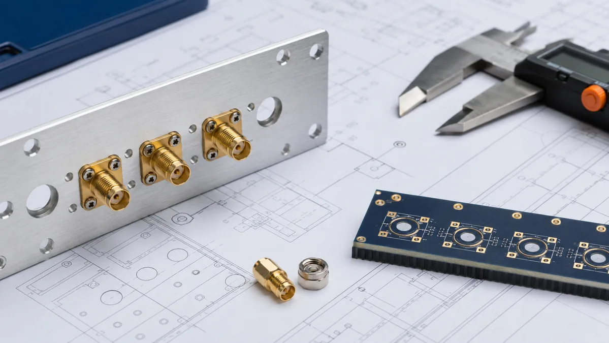
The safest workflow is to treat each SMA connector part number as its own controlled mechanical item. Even when two connectors share the same general interface family, their mounting body, rear termination, flange, gasket area, board height, or cable-exit envelope may differ. For I/O connector projects, the key is to review the mating interface and the application-side mounting geometry together.
| Review Area | What to Check | Why It Matters |
|---|---|---|
| Mating interface | Gender, center contact geometry, dielectric position, coupling area, and mating face condition. | Confirms the selected connector will mate with the intended cable assembly without relying on visual similarity. |
| PCB footprint | Center pad, ground pads or posts, keepout area, board-edge position, solder access, and ground return path. | Reduces the risk of layout rework and supports a cleaner RF transition at the board interface. |
| Panel cutout | Hole shape, flats, washer clearance, panel thickness range, mounting shoulder, and hardware stack. | Helps avoid loose fit, tilted connectors, incomplete hardware engagement, or interference with the enclosure. |
| Rear clearance | Cable bend envelope, right-angle body sweep, soldering access, strain relief, and nearby component height. | Prevents a connector that fits on paper from becoming difficult to assemble or service. |
| Documentation | Approved drawing revision, datasheet, inspection plan, test expectations, and packaging requirements. | Keeps engineering, purchasing, and quality teams aligned around the same part definition. |
Male, Female, and Reverse-Polarity Details
When sourcing SMA connectors, gender should be confirmed by the center contact rather than by the thread alone. This point is simple, but it is a frequent ordering risk when a drawing, BOM, and purchasing description use inconsistent wording. A standard SMA interface, an SMA female connector, and a reverse-polarity variant can look similar in a low-resolution image while requiring different mating hardware.
For sma female connector dimensions, do not copy values from a generic catalog image into your drawing. Ask for the supplier drawing that matches the part number, mounting style, plating option, and termination type. The same review should confirm whether the connector is intended for cable mount, PCB mount, bulkhead mount, flange mount, or an edge-launch layout.
SMA Connector Types and Size Tradeoffs
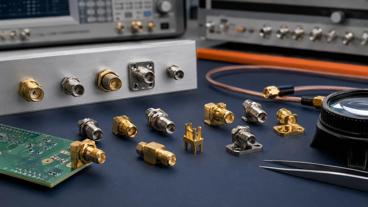
Different SMA connector types solve different mechanical problems. A straight PCB connector may keep the signal path direct, but it needs rear clearance. A right-angle connector can reduce height, but it changes the footprint and can crowd nearby components. A bulkhead connector supports a panel interface, but the enclosure thickness and hardware stack become part of the design. A flange connector spreads mounting load, but screw-hole location and assembly access must be managed carefully.
| Connector Style | Typical Review Focus | Procurement Question |
|---|---|---|
| Straight PCB mount | Board height, solder pad geometry, rear clearance, and test access. | Does the drawing match the released PCB stackup and assembly process? |
| Right-angle PCB mount | Footprint length, body sweep, connector height, and nearby component interference. | Has the mechanical team checked the cable exit direction and enclosure clearance? |
| Bulkhead mount | Panel thickness, shoulder seating, hardware stack, and cable strain relief. | Can the supplier provide the exact panel cutout recommendation for this part number? |
| Flange mount | Mounting holes, screw access, gasket area, and panel flatness. | Is the screw pattern controlled in both the connector drawing and enclosure drawing? |
| Edge launch | Board edge finish, ground pad alignment, launch geometry, and fixture access. | Has the launch area been reviewed with the RF layout and assembly teams? |
How Frequency Requirements Change the Dimension Review
The sma connector frequency range should be confirmed for the exact connector series, cable assembly, PCB launch, and test condition. A catalog family may include multiple constructions, and performance can change with termination style, cable type, board layout, or adapter stack. For this reason, the safest RFQ language is not “SMA is enough,” but “confirm the required operating band and provide the relevant drawing and test documentation.”
When the application moves toward higher-frequency or broadband behavior, dimensional control becomes more sensitive. Teams should review the mating plane, dielectric support, launch transition, ground continuity, and cable interface as one system. If the project requires a performance report, define that requirement during sourcing instead of waiting until samples arrive.
How This Connects to I/O Connector Projects
SMA connectors often sit beside other external interfaces, shielded connectors, cables, and panel hardware. That makes them part of the larger I/O architecture rather than an isolated RF component. For broader selection criteria across external and panel interfaces, see LinkManu’s I/O Connectors for External and Panel Interface Projects.
If your team is comparing SMA connector sizes with other I/O connector options, it helps to separate the decision into mechanical fit, electrical requirement, environmental exposure, assembly method, and supply readiness. This keeps purchasing from choosing a visually similar part before engineering has confirmed the actual drawing.
Supplier Review Checklist for SMA Connector Dimensions
A supplier review should make the open questions visible before a purchase order is placed. The checklist below is useful when comparing samples, requesting a quote, or preparing a custom connector discussion.
- Confirm the exact part number, drawing revision, and approved datasheet used for the quote.
- Ask whether the connector gender and polarity match the cable assembly and system interface.
- Review the PCB footprint, panel cutout, hardware stack, and rear-clearance envelope together.
- Define the target operating band, test method, and documentation expectations before sampling.
- Confirm material, plating, packaging, and inspection requirements for the application environment.
- Ask how samples will be checked before shipment and what information should be included in the RFQ.
For custom connector discussions, LinkManu can review drawings, BOM details, mounting requirements, and sample readiness in relation to available manufacturing capabilities such as tooling, stamping, injection molding, and assembly. LinkManu company materials also reference IATF 16949 and ISO 14001 certifications.
Teams that are still comparing connector families can also review the broader Products section, while teams with drawings or sourcing questions can reach Contact Engineering Support for project review.
FAQ
Can I use a generic SMA connector dimension drawing for PCB layout?
No. Use the controlled drawing for the exact part number. Generic diagrams can help explain terminology, but they should not define pad size, panel cutout, board edge location, or hardware clearance.
What is the main difference between SMA connector size and SMA connector dimensions?
SMA connector size often refers to the overall physical envelope, while SMA connector dimensions should include the mating interface, termination geometry, mounting details, and project-specific clearance requirements.
How should I compare different SMA connector types?
Compare them by mounting method, PCB footprint, panel requirements, cable exit direction, test expectation, and supplier documentation. The lowest-risk choice is the one that fits both the electrical requirement and the mechanical assembly.
What should be included in an SMA connector RFQ?
Include the drawing, BOM, target application, operating band, mounting style, panel or PCB constraints, sample quantity, documentation needs, and any environmental or quality requirements that affect inspection.
Send Your Connector Requirement
Share your drawing, BOM, target application, or technical requirements. LinkManu can review connector fit, sample options, documentation needs, and RFQ readiness before final selection.

Technical content reviewed by LinkManu Engineering Team
Prepared by LinkManu Editorial Team for B2B connector engineers, sourcing teams, and product development projects. Updated 2026.