
Cable Assembly Engineering
Cable Connector Types for Industrial Assembly Projects
Choosing among the many types of cable connectors is rarely a catalog-only decision. In a real cable assembly project, the connector has to match the cable construction, mating interface, panel design, operating environment, handling process, and inspection plan. A connector that looks suitable in a product photo can still create risk if the drawings, tooling, strain relief, shielding, and test requirements are not reviewed together.
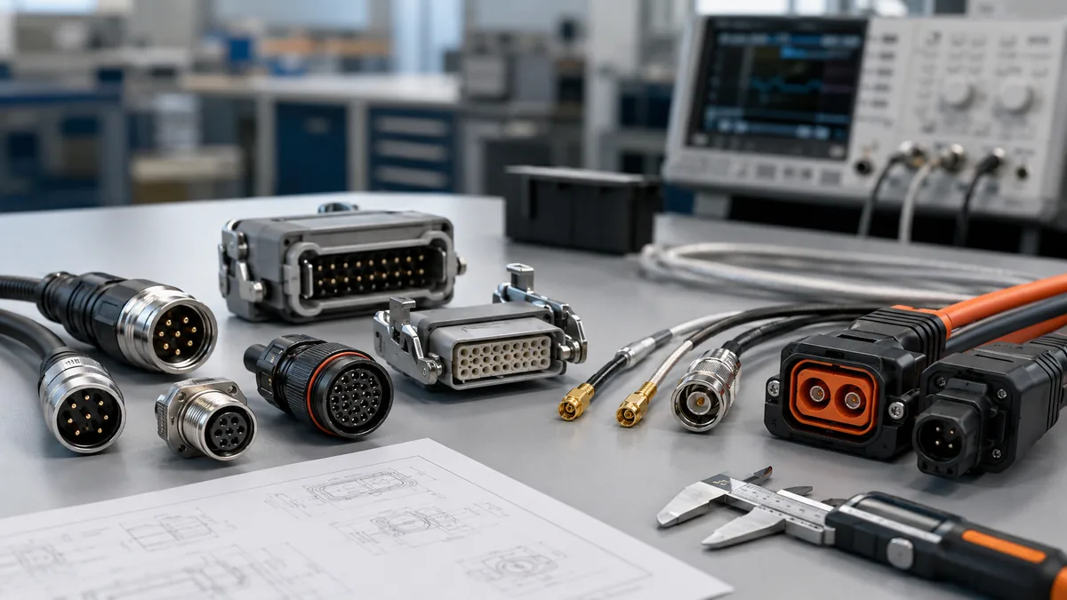
This guide explains the major connector families used in cable assembly applications and the engineering questions that buyers should confirm before sampling. It is written for sourcing teams, product engineers, and quality managers who need practical RFQ checks rather than unsupported performance claims.
Engineering note: Any rating, torque, temperature limit, impedance target, current level, sealing level, or mating-cycle value should be confirmed against the specific customer drawing, supplier datasheet, and intended application. This article uses connector families and selection questions, not unverified numeric claims.
Why Connector Choice Affects the Whole Assembly
A connector is the interface where the cable assembly meets the equipment. It has to carry the required signals or power, fit the enclosure, tolerate the installation method, and remain stable under the field conditions defined by the project. When the connector is selected too late, teams often discover that the cable outlet, backshell, panel opening, strain relief, or test method does not match the final design.
That is why LinkManu treats connector selection as part of the full cable assembly review. Manufacturing capabilities such as assembly, injection molding, stamping, and tooling can support a more complete project discussion when the drawing, BOM, connector preference, and application environment are shared early. For turnkey projects, the Custom Cable Assemblies & Wire Harnesses Manufacturer | LinkManu page is the recommended pillar resource for reviewing connector, harness, and overmold requirements together.
Common mismatch risks
- The connector face matches, but the cable exit does not support the required bend direction.
- The housing fits the panel, but panel thickness, mounting hardware, or sealing method has not been confirmed.
- The selected connector family supports the general application, but the exact shielding, termination, or cable diameter range is not aligned with the assembly drawing.
- The procurement team compares part numbers, while the production team still needs crimp tooling, molding fixtures, inspection gauges, and test instructions.
Main Types of Cable Connectors Used in Assemblies
The following overview groups the most common types of cable connectors by function and assembly context. The goal is not to rank one family above another. The right choice depends on what the cable assembly must do, where it will be installed, and how it will be produced and serviced.
| Connector Family | Typical Assembly Context | RFQ Questions to Confirm |
|---|---|---|
| Circular connectors | Sensor cables, actuator wiring, field equipment, machine-side connections, and compact panel interfaces. | Confirm mating method, sealing target, cable outlet size, panel fit, shielded or unshielded version, and whether factory termination or field installation is preferred. |
| Rectangular connectors | Control cabinets, modular machine wiring, mixed power and signal interfaces, and high-contact-count harnesses. | Confirm insert layout, contact arrangement, backshell style, panel mounting method, strain relief, and tooling needed for production assembly. |
| RF and coaxial connectors | Signal-sensitive cable assemblies, antenna-related links, test equipment, and measurement paths. | Confirm impedance requirement, bandwidth expectation, cable type, shielding continuity, termination process, and validation method for the finished cable assembly. |
| Power connectors | Battery-related wiring, drives, power modules, industrial equipment, and higher-load cable routes. | Confirm voltage and current requirements from the system BOM, thermal conditions, contact design, wire size, insulation system, and enclosure environment. |
| Board, wire, and cable interface connectors | Internal harnesses, PCB-to-cable transitions, compact equipment wiring, and product-level interconnects. | Confirm pitch, pin count, locking method, cable preparation, mating orientation, and whether assembly handling could stress the termination. |
Circular connectors
Circular connectors are widely used when the interface needs compact geometry, defined mating orientation, and a coupling system suitable for field equipment. They may be specified in sensor, actuator, industrial control, and equipment wiring applications. However, the form factor alone does not prove environmental performance. The project team should confirm the exact sealing requirement, mating method, cable outlet, shell material, shielding approach, and installation procedure.
Rectangular connectors
Rectangular connectors are useful when a project needs a dense, organized interface for multiple conductors. They can support modular layouts where power, signal, and data paths need to pass through one panel interface. The main review areas are insert arrangement, locking hardware, backshell clearance, panel cutout, assembly tooling, and long-term service access.
RF and coaxial connectors
RF and coaxial cable assemblies require special attention because the connector, cable, termination method, and shielding path work together. Instead of assuming a generic signal rating, engineering should define the target impedance, expected bandwidth, cable construction, bend control, and acceptance test for the finished assembly. This avoids a situation where a component appears correct but the assembled cable does not meet the system need.
Power connectors
Power connectors should be selected from the system requirement outward. The BOM should define the operating load, wire size, insulation needs, enclosure conditions, and expected thermal environment. A connector rating listed by a supplier still needs project-level confirmation because heat rise, bundling, contact resistance, and ventilation are properties of the complete assembly environment.
Selection Factors Engineers Should Compare
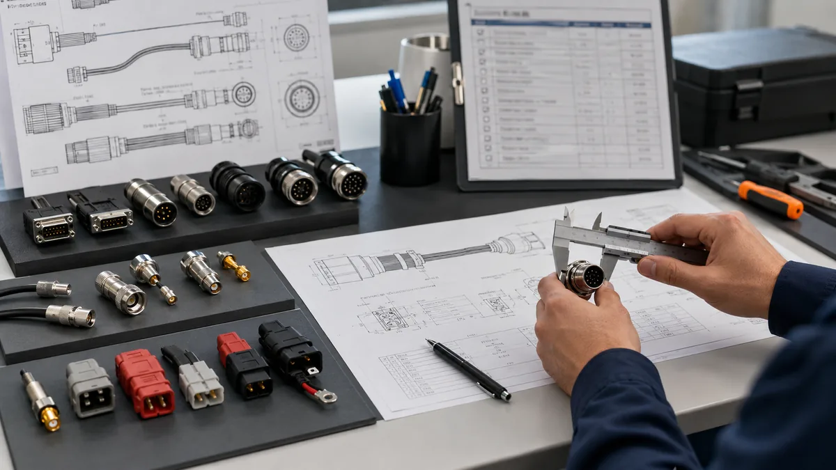
For B2B cable assembly projects, the strongest RFQs describe how the connector will be used. This gives the supplier enough context to review the application instead of simply quoting an approximate part number. The following factors apply across many types of cable connectors.
Application environment
- Will the assembly be installed indoors, outdoors, inside equipment, or on a moving machine?
- Should the sealing level be confirmed against exposure to dust, liquid, cleaning agents, or washdown conditions?
- Could ultraviolet exposure, alkalies, amines, oils, or other chemicals affect housing or cable materials?
- Does the assembly need overmolding, potting, or added strain relief to support the operating environment?
Electrical and signal requirements
- What voltage, current, signal type, shielding requirement, and grounding concept are defined by the system?
- For data or RF paths, what impedance and bandwidth targets should be verified on the finished cable assembly?
- Should contact resistance, continuity, hipot, or signal integrity tests be included in the inspection plan?
- Are power and signal conductors routed together, and does that create additional EMI or heat concerns?
Mechanical design and handling
- Confirm the connector orientation, cable outlet direction, minimum bend control, and strain relief method.
- Review panel thickness, mounting hardware, screw tightening instructions, and any required installation tools.
- Check whether the connector is intended for field assembly or factory termination, because the tooling and inspection process may differ.
- Define how operators should mate, unmate, package, and service the assembly to avoid damage.
RFQ tip: A useful connector RFQ should include the drawing, BOM, target application, cable construction, connector family under consideration, environmental notes, compliance expectations, and any known sample or documentation requirements.
Assembly and Verification Practices
Even a well-selected connector can fail to meet expectations if the assembly process is not controlled. The finished cable assembly should be reviewed for cable preparation, termination quality, shielding continuity, strain relief, connector orientation, and inspection criteria.
Pre-assembly planning
- Review strip length, shielding preparation, crimp or solder process, and any molded or potted features before production starts.
- Confirm that the cable outer diameter and jacket material are suitable for the selected connector and outlet design.
- Keep connector lots protected from contamination, chemical exposure, unnecessary UV exposure, and mechanical damage during storage.
- Remove damaged or defective connector components from production rather than attempting repair at the assembly level.
Handling rules that protect reliability
- Do not mate or unmate connectors while the circuit is under electrical load.
- Do not pull a cable at an angle that transfers stress into the termination area.
- Use the correct tightening sequence and tools for the connector series and panel design.
- Train operators and field personnel on the specific connector style used in the project.
How LinkManu Supports Connector Review
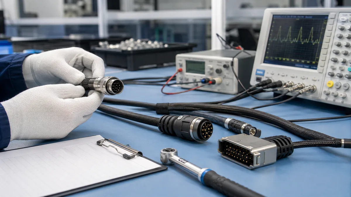
For projects that involve custom cable assemblies, connector review works best when sourcing, engineering, and manufacturing are aligned before tooling or samples are committed. LinkManu can help evaluate connector fit, cable routing, documentation needs, tooling feasibility, and assembly process risks based on the drawing and application information provided by the customer.
When a standard connector family is not enough, custom connector or overmold design may be reviewed as part of the project scope. LinkManu capabilities include assembly, injection molding, stamping, and tooling, with certification references including IATF 16949 and ISO 14001. For non-standard housing, contact arrangement, or integration requirements, see Custom Connectors. For broader product categories, the Products page can help place the assembly requirement in the correct product family.
Before requesting samples
- Share the latest drawing and BOM, including any connector series already under consideration.
- Explain the operating environment, mating frequency, installation method, and service expectations.
- Identify required documents such as material declarations, inspection reports, or certification references.
- Ask the supplier to confirm which parameters require project-specific validation before production.
If the requirement is still early, start with a short engineering review through Get Engineering Review. A clear review at the RFQ stage can reduce avoidable sample revisions and keep connector decisions tied to the complete cable assembly.
Frequently Asked Questions
What are the main types of cable connectors used in industrial assemblies?
The common groups include circular connectors, rectangular connectors, RF and coaxial connectors, power connectors, and board or wire interface connectors. Many industrial systems combine several types of cable connectors in one equipment platform, so each interface should be reviewed against its own electrical, mechanical, and environmental requirements.
How should I choose between circular and rectangular connectors?
Circular connectors are often considered for compact field wiring and defined mating interfaces, while rectangular connectors are often used for dense panel or cabinet connections. The better choice depends on the drawing, enclosure design, conductor count, cable routing, mating method, sealing target, and service process.
Can one connector family cover power and signal requirements together?
Some connector systems can combine different contact functions, but the project must confirm contact arrangement, spacing, shielding, thermal behavior, and inspection requirements. For mixed power and signal assemblies, the RFQ should clearly separate power, signal, grounding, and EMI expectations.
What information should I send for connector selection review?
Send the drawing, BOM, cable specification, connector preference, application environment, expected tests, sample quantity, and any documentation requirements. This helps the supplier review connector fit as part of the complete assembly instead of quoting from a limited part description.
Send Your Connector Requirement
Share your drawing, BOM, cable construction, operating environment, and connector family under consideration. LinkManu can review the requirement and help clarify sample, tooling, and RFQ details.

Technical content reviewed by LinkManu Engineering Team
Prepared by LinkManu Editorial Team for B2B connector engineers, sourcing teams, and product development projects. Updated 2026.