
Wire-to-Board Connector Guide
Types of Wire Connectors for Wire-to-Board PCB Applications
In PCB assemblies, the types of wire connectors used between a cable harness and a board can affect assembly workflow, serviceability, inspection needs, and long-term reliability. Generic lists of electrical connectors often mix household splices, heavy-gauge lugs, wire-to-wire products, and PCB connector systems. For engineering and purchasing teams, the useful question is narrower: which wire connector type fits the actual wire-to-board interface?
This guide focuses on crimp housings, IDC connectors, terminal blocks, and direct-solder wire terminations used around PCB assemblies. It does not treat every connector as interchangeable. Instead, it maps each option to the termination method, production flow, field-service expectation, and sourcing questions that should be clarified before samples or tooling are approved.
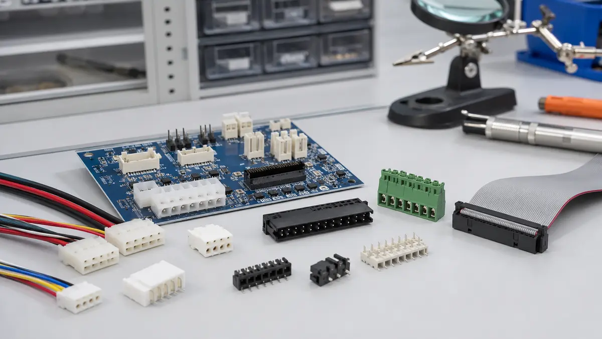
How Types of Wire Connectors Fit Wire-to-Board Projects
A wire-to-board connection is the point where discrete wires, ribbon cable, or a harness assembly meet a PCB-mounted header or terminal block. At this junction, mechanical retention, contact quality, wire preparation, housing geometry, and board layout all matter. A connector that looks acceptable during a static continuity check may still be unsuitable if it does not match the vibration, rework, environmental, or assembly requirements of the product.
For a sourcing team, the phrase types of wire connectors should therefore be filtered by application. A residential twist-on connector, a ring terminal, and a crimp housing for a PCB header are all wire connector products, but they solve different problems. When evaluating LinkManu Products, the first step is to separate wire-to-board connector families from inline splices, board-to-board connectors, and general electrical installation hardware.
Scope note: This article uses “types of wire connectors” in the PCB wire-to-board sense. Always confirm final current, voltage, pitch, wire gauge, material, plating, and environmental requirements with the connector datasheet and supplier engineering review.
Connector Types by Termination Method
The most practical way to compare wire-to-board connector types is by termination method. Termination defines how the conductor is joined to the connector contact, how the assembly is inspected, and whether field rework is expected.
| Termination Style | Typical Wire-to-Board Use | Assembly Method | Rework Consideration | Key Review Question |
|---|---|---|---|---|
| Crimp contact in housing | Harness-to-PCB interfaces in appliances, automotive modules, industrial controls, and other volume assemblies | Wire is stripped, crimped to a metal contact, inserted into a plastic housing, then mated to a PCB header | Contacts may be serviced with the correct extraction tool; housing reuse depends on the connector design and inspection result | Does the crimp barrel, insulation support, and housing lock match the selected wire and assembly process? |
| IDC connection | Ribbon cable, discrete-wire mass termination, control panels, and compact signal wiring | Insulated conductor is pressed into a contact slot designed for the wire and insulation system | Rework is usually limited because the contact beam is affected by insertion history | Has the wire insulation type been validated with the IDC contact geometry? |
| Screw terminal block | Field wiring for industrial equipment, power supplies, control cabinets, and serviceable PCB interfaces | A screw-driven clamp secures the stripped conductor or ferruled wire in the terminal body | High serviceability, but torque control and visual inspection are important | Is the specified tooling, strip length, and ferrule practice clear in the assembly instruction? |
| Spring-clamp or push-in terminal block | Field wiring where fast insertion and repeatable clamp force are priorities | Wire or ferrule is inserted into a spring mechanism; a release feature allows removal | Serviceable when the release feature is used correctly | Does the selected terminal accept the conductor preparation used by production or field technicians? |
| Direct-solder wire termination | Cost-sensitive or space-limited designs where no detachable connector is required | Prepared wire is soldered directly to a PCB pad, plated hole, or post | Lower rework convenience; strain relief and process control become more important | Is the product designed to prevent wire movement from stressing the solder joint? |
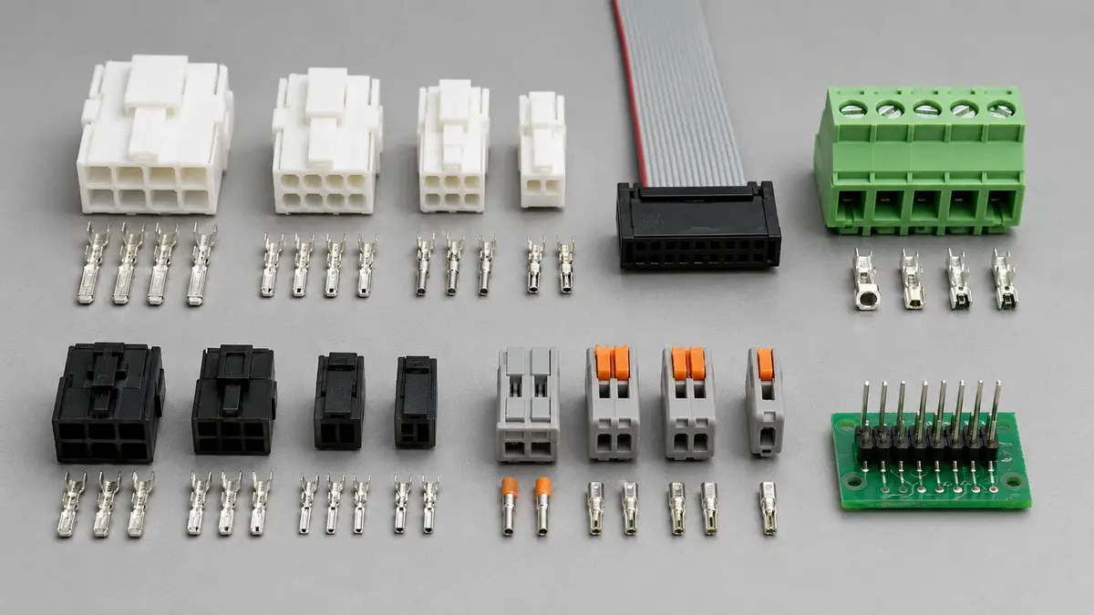
Crimp, IDC, and Terminal Block Selection Logic
Crimp-Style Wire-to-Board Connectors
Crimp-style systems are common when harness assembly and PCB assembly are handled as separate production steps. The metal contact is crimped to the wire, inserted into a molded housing, and then mated with a board-mounted header. This structure can support controlled harness production, inspection before final assembly, and replacement of individual contacts when the connector family permits it.
When reviewing crimp-based types of wire connectors terminals, focus on conductor preparation, insulation support, terminal retention, housing latch design, and available tooling. The sourcing conversation should also cover whether the supplier can support stamping, tooling, injection molding, and assembly coordination. LinkManu capability references include stamping, tooling, injection molding, and assembly, which are relevant when a project requires connector customization or production readiness review.
IDC Connectors
IDC, or insulation displacement connection, can reduce wire preparation steps because the conductor is pressed into a contact slot rather than stripped and crimped first. IDC is often considered for ribbon cable, compact signal wiring, and factory-terminated harnesses. It is less forgiving when wire insulation material, conductor construction, or insertion tooling changes without validation.
For IDC wire to board connector types, the engineering review should confirm the wire specification, insertion method, strain relief, and inspection method. Treat IDC as a system involving wire, contact, housing, and tooling. Avoid changing one part of that system without checking how it affects termination quality.
Terminal Block Connectors
Terminal blocks are often selected when the wire-to-board interface must be serviceable during installation, maintenance, or equipment commissioning. Screw-clamp, spring-clamp, and push-in designs can all be appropriate, but they require different assembly instructions and inspection checkpoints.
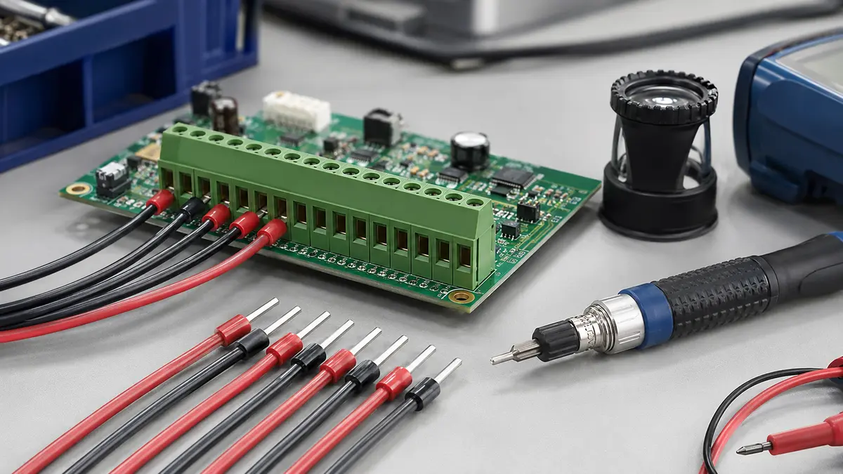
Screw terminal blocks depend on correct wire preparation and torque control. Spring-clamp and push-in types depend on conductor preparation, ferrule suitability where required, and proper use of the release mechanism during rework. In procurement terms, terminal block selection should include technician workflow, field environment, board footprint, and documentation expectations, not only pitch and pole count.
How to Insert Wire into Terminal Block During Assembly
The search question “how to insert wire into terminal block” looks simple, but the correct answer depends on the terminal style. The following process is a practical starting point for assembly technicians and quality teams. Final instructions should always come from the selected connector datasheet and the production control plan.
Prepare the Wire and Tooling
- Confirm strip length from the connector documentation. Too much exposed conductor can create clearance risk, while too little exposed conductor can leave insulation inside the clamp area.
- Check whether stranded wire requires a ferrule for the selected terminal block. Ferrule choice should match the conductor, insulation diameter, and terminal entry.
- Select the screwdriver, release tool, or insertion tool specified for the terminal style. For screw-clamp types, use controlled tooling where the production process requires it.
- Inspect stripped conductors for cut strands, folded strands, or deformation before insertion.
Insert and Verify
- For push-in or spring-clamp terminals, align the conductor or ferrule with the entry and insert it straight until it reaches the designed stop.
- For screw terminal blocks, place the conductor fully into the wire entry before tightening. Confirm that no stray strands are outside the clamp area.
- Use the approved release feature for rework. Pulling a wire out without releasing the clamp can damage the terminal contact system.
- Perform the inspection required by the production plan, such as visual confirmation, gentle retention check, and continuity check.
Selection Questions Before You Lock the BOM
Before approving any types of electrical wire connectors for a PCB project, convert the specification into review questions. This avoids copying unsupported catalog assumptions into a BOM.
Electrical Review
- What operating voltage, current load, and temperature environment must the connector support in the real assembly?
- Are all contacts energized at the same time, or does the load vary by circuit?
- Does the PCB layout provide enough space for creepage, clearance, copper routing, and heat management?
- If power and signal circuits share one connector housing, has the pin assignment been reviewed for thermal and electrical interaction?
Mechanical Review
- Will the connector be mated once during factory assembly, or will technicians disconnect it during service?
- Does the application require a latch, keying feature, secondary lock, or polarization to reduce assembly error?
- Can the board, housing, and harness routing tolerate the insertion and extraction forces?
- Is there enough strain relief so wire movement does not transfer directly into the contact or solder joint?
Environmental Review
- Will the connector be exposed to moisture, dust, chemicals, condensation, or vibration?
- Does the selected housing material match the soldering process and operating environment?
- Is plating choice being reviewed against signal level, expected movement, and corrosion risk?
- Are validation tests and inspection records defined before pilot production?
Engineering review point: Values such as current rating, voltage rating, pitch, pull force, mating cycle expectation, and operating temperature should be treated as part-specific requirements. Confirm them from the selected datasheet and project validation plan rather than using generic ranges from search results.
Procurement and Documentation Review
Procurement teams should ask suppliers to connect the connector recommendation to actual manufacturing and quality evidence. For wire-to-board projects, useful RFQ inputs include wire gauge, strand construction, insulation outside diameter, pin count, target board footprint, expected service access, environmental exposure, annual usage, and sample timeline.
For automotive, industrial, or environmentally controlled projects, the documentation package may also include process controls, material declarations, inspection records, and certification references. LinkManu documentation references include IATF 16949 and ISO 14001, and technical teams can clarify which records are relevant for the project through Contact Engineering Support.
If the project is still in early design, review the available Wire-to-Board Connectors for PCB-to-Wire Interfaces family once to align connector structure with the target application. From there, the RFQ should narrow the connector type, termination method, wire preparation, sample requirement, and validation question list.
Frequently Asked Questions about Wire-to-Board Connectors
What are the main types of wire connectors for PCB applications?
In wire-to-board PCB applications, the main categories are crimp-contact housings, IDC connectors, screw terminal blocks, spring-clamp or push-in terminal blocks, and direct-solder wire terminations. The right choice depends on assembly process, service access, wire preparation, board layout, and validation requirements.
How are types of electric wire connectors different from wire-to-board connector types?
Types of electric wire connectors is a broad phrase that may include splices, lugs, installation connectors, and wire-to-wire products. Wire-to-board connector types specifically describe the interface between a wire or cable harness and a PCB-mounted connector or terminal block.
When should a terminal block be used instead of a crimp housing?
A terminal block is often considered when field wiring, service access, or installation flexibility is required. A crimp housing is often considered when harness assembly is controlled before final PCB assembly. The final choice should be confirmed against wire size, current load, board space, service needs, and validation plan.
What should be prepared before requesting a connector quotation?
Prepare wire gauge, strand construction, insulation diameter, pin count, target pitch or footprint, application environment, service expectations, sample quantity, drawings, and any required documentation. These details help the supplier review connector fit without making unsupported assumptions.
Send Your Connector Requirement
Share your drawing, BOM, target application, or technical requirements. LinkManu can review connector fit, sample options, documentation needs, and RFQ readiness before final selection.

Technical content reviewed by LinkManu Engineering Team
Prepared by LinkManu Editorial Team for B2B connector engineers, sourcing teams, and product development projects. Updated 2026.