
Industrial Connector Guide
What Is a Terminal Block? Industrial Uses, Types, and Selection Guide
A terminal block is an insulated modular connector that joins two or more conductors at a secure, serviceable connection point. In industrial equipment, the answer to what is a terminal block is not only “a wire connector.” It is a controlled interface for routing power, signals, grounding, or field wiring inside a panel, machine, or electronic assembly.
For engineers and sourcing teams, the practical value is maintainability. A well-specified terminal block helps technicians land wires in an organized way, inspect connections, separate circuits when service is needed, and keep a wiring system understandable after the first build. Poorly specified blocks may still look correct in a catalog image, but they can create risk when the final equipment faces vibration, contamination, thermal cycling, or repeated maintenance access.
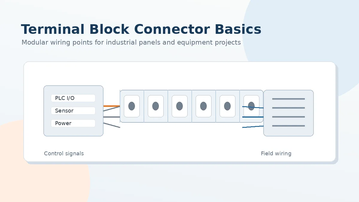
What Terminal Blocks Do in Industrial Equipment
Terminal blocks give electrical wiring a repeatable structure. Instead of leaving conductors as loose splices or one-off hand connections, the block provides an insulated housing, a current-carrying element, and a clamping or termination mechanism. This makes the connection easier to document, inspect, replace, or expand during the product life cycle.
When buyers ask what terminal blocks do, the most useful answer is functional: they organize conductors, maintain contact force, separate circuits, support field service, and help the panel layout remain readable. In a machinery enclosure or control cabinet, that readability matters because future troubleshooting often depends on whether the wiring system still matches the drawing and labeling scheme.
Engineering note: Treat a terminal block as part of the complete interconnect system. The correct choice depends on conductor type, panel layout, operating environment, documentation needs, and supplier evidence, not only on appearance or pole count.
Why Standard Wire Joining Is Not Enough for Production Equipment
Prototype wiring can be forgiving. A temporary screw connection or soldered joint may work during bench testing, especially when the assembly is not exposed to repeated movement or field maintenance. Production equipment is different. The connection may need to survive handling, transportation, installation, vibration, cabinet access, and replacement work by technicians who did not build the original prototype.
This is why what are terminal blocks used for is a practical engineering question. They are used where a project needs organized wire termination, stable electrical contact, clear circuit separation, and easier service access. For industrial equipment projects, terminal block selection should be reviewed alongside cable assemblies, board-level connectors, enclosure layout, and the expected maintenance process. The broader application fit is covered in LinkManu’s Industrial Equipment Connector Solutions.
- Mechanical stress: Vibration and repeated access can challenge connections that were not selected for the equipment environment.
- Environmental exposure: Dust, oil, moisture, or chemical residue can affect contact surfaces and insulating materials.
- Serviceability: A connection method that works in assembly may become slow or confusing when technicians need to diagnose a field issue.
- Documentation control: Terminal numbering, circuit grouping, and labeling can reduce wiring ambiguity during production and maintenance.
Basic Anatomy of a Terminal Block
A terminal block normally combines three essential elements: an insulating body, a conductive path, and a termination mechanism. The insulating body separates adjacent circuits and provides the physical structure. The conductive element carries current or signal between the connected conductors. The termination mechanism secures the wire by screw clamp, spring clamp, push-in contact, stud, or another design depending on the application.
Understanding what is terminal blocks in real product development also means understanding that these parts are not evaluated as isolated shapes. Housing material, contact design, plating quality, conductor preparation, and assembly process all affect the final connection. A sourcing decision based only on color, pitch, or visual similarity can miss the features that determine long-term reliability.
Key Elements Engineers Should Review
- Housing material: Confirm whether the insulation material is appropriate for the application environment and safety documentation requirements.
- Conductive element: Review the current bar or contact material, plating approach, and supplier control over stamping or forming.
- Clamping method: Match screw, spring, push-in, or stud termination to the conductor type and service process.
- Wire preparation: Confirm whether bare stranded wire, solid wire, ferrules, or lugs are required for the selected block.
- Labeling and layout: Check whether the block supports clear circuit identification and practical maintenance access.
Common Terminal Block Types and Where They Fit
There are many terminal block formats because equipment layouts vary. A DIN-rail block in a control cabinet solves a different problem than a PCB terminal block on an embedded drive board or a barrier strip in a junction box. The right format depends on where the wires land, how often the connection may be serviced, and what the enclosure or board layout allows.
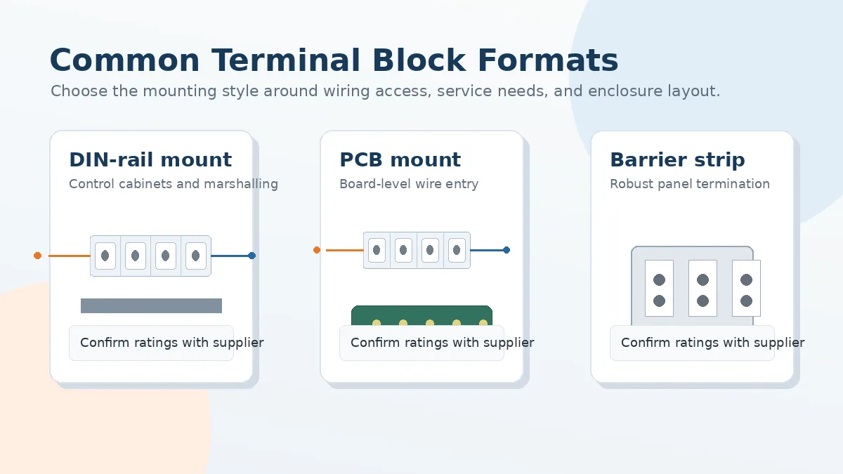
Mounting Styles Compared
| Mounting Style | Typical Role | Service Access | Common Project Fit |
|---|---|---|---|
| DIN-rail terminal block | Modular wiring and circuit grouping inside panels | Usually accessible for field wiring and maintenance | Control cabinets, automation panels, sensor and actuator wiring |
| PCB-mount terminal block | Wire-to-board connection on electronic assemblies | Depends on enclosure opening, board position, and connector orientation | Drive boards, control boards, power modules, embedded interfaces |
| Barrier strip or through-panel block | Robust panel or junction-box termination | Often suited to tools and ring or fork terminals, depending on design | Power entry, machinery junctions, field connection points |
| Function-specific block | Termination combined with disconnect, fuse, grounding, or signal distribution function | Designed around a specific inspection or service workflow | Test points, protected circuits, grounding rows, compact marshalling |
Single-Level, Multi-Level, and Function-Specific Blocks
Single-level pass-through terminal blocks are easy to read and are common where circuit separation matters more than panel density. Multi-level blocks can save space, but they require careful review of heat, access, labeling, and service workflow. Disconnect and fuse terminal blocks add useful functions at the wiring point, while sensor or actuator terminal blocks can simplify repetitive I/O wiring. In each case, engineers should confirm the rating, material, and documentation for the actual part number under consideration.
Selection Checklist: What to Confirm Before Sourcing
A strong selection process starts with the drawing and the real installation conditions. The goal is not just to answer what are terminal blocks in general, but to define what the terminal block must do in this project. That includes electrical load context, conductor handling, panel layout, service access, environmental exposure, and the supplier’s ability to document the design.
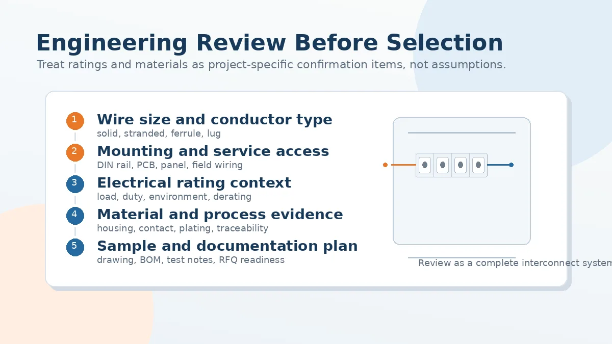
Critical Questions for the Supplier
- Conductor compatibility: Which wire sizes, conductor types, ferrules, lugs, or stripping requirements are approved for the block?
- Electrical rating context: Are the rated current and voltage appropriate for the actual circuit, duty, enclosure, and ambient conditions?
- Mechanical retention: How is wire pull-out, vibration exposure, and repeated service access considered in the design or testing plan?
- Material evidence: What documentation is available for housing material, contact material, plating, and relevant safety requirements?
- Panel layout: Does the pitch, pole count, height, and wiring direction fit the enclosure and technician access path?
- Traceability: Can the supplier provide drawing control, lot traceability, inspection records, and change-control communication?
- Sample validation: Can the project team review samples before finalizing the BOM and production purchase?
Important: Exact values for current, voltage, pitch, temperature, ingress protection, flammability, and creepage or clearance should be confirmed from the selected supplier documentation. Do not assume these values from a similar-looking part.
Why Supplier Process Control Matters
Terminal blocks are small components, but the manufacturing process behind them affects consistency. Housing molding, metal stamping, plating, assembly, and inspection all influence whether the delivered parts match the drawing over time. For OEMs, contract manufacturers, and harness builders, inconsistent batches can create hidden risk even when the first sample appears acceptable.
LinkManu’s available source facts for this topic include manufacturing capabilities such as assembly, injection molding, stamping, and tooling. Company documentation also references IATF 16949 and ISO 14001. For any live project, buyers should request current certificates and project-specific quality records as part of supplier qualification. This approach aligns with LinkManu’s Engineering & Quality review process.
Process Evidence to Request
- Controlled drawings or specifications for the selected terminal block series.
- Material and plating documentation for the housing and conductive elements.
- Inspection approach for critical dimensions, contact areas, and assembly quality.
- Sample review plan before production sourcing or large-volume replacement.
- Change-control communication for tooling, material, or process updates.
If the terminal block is part of a larger interconnect system, it may need to be reviewed together with wire harnesses, PCB connectors, cable routing, and enclosure constraints. LinkManu’s Custom Connector Support can help evaluate drawings, BOM information, and sample requirements. You can also browse View Connector Products for related connector families.
Frequently Asked Questions
What is a terminal block connection?
A terminal block connection is the secured junction between a conductor and a conductive element inside an insulated terminal block housing. Depending on the design, the wire may be held by a screw clamp, spring clamp, push-in mechanism, stud, or other termination method. The purpose is to create a connection that can be assembled, inspected, labeled, and serviced more easily than a permanent splice.
What are the different types of terminal block connectors?
Common types include DIN-rail terminal blocks, PCB-mount terminal blocks, barrier strips, grounding blocks, disconnect blocks, fuse blocks, and multi-level blocks. The right fit depends on mounting location, wire type, service access, circuit function, enclosure layout, and supplier documentation for the selected part.
What is terminal block in electrical panel design?
In an electrical panel, a terminal block is a structured landing point for incoming and outgoing wiring. It helps organize circuits, route field wiring, support labeling, and make future troubleshooting more manageable. The block should be selected together with the panel layout, wiring diagram, and maintenance process.
Can terminal blocks handle high voltage or high current?
Some terminal blocks are designed for demanding power applications, but the safe answer depends on the exact part number and project environment. Engineers should confirm rated current, rated voltage, insulation requirements, conductor preparation, and enclosure conditions from supplier documentation before approving the part for production.
Can I use industrial terminal blocks in residential wiring?
Residential wiring is governed by local electrical codes and approved installation methods. Industrial terminal blocks are usually intended for equipment, panels, or assemblies with defined enclosures and documentation. Before using any industrial connector in a residential setting, consult qualified electrical professionals and the applicable local code requirements.
Send Your Connector Requirement
Share your drawing, BOM, target application, or technical requirements. LinkManu can review terminal block fit, sample options, documentation needs, and RFQ readiness before final selection.

Technical content reviewed by LinkManu Engineering Team
Prepared by LinkManu Editorial Team for B2B connector engineers, sourcing teams, and product development projects. Updated 2026.