
Cable Assembly Guide
How to Disconnect Ribbon Cable Assemblies Without Connector Damage
Knowing how to disconnect ribbon cable assemblies safely is a practical skill for repair technicians, test engineers, and sourcing teams that work with compact electronic products. The process is not only about pulling a cable out of a socket. The first step is to identify the connector style, release the retention feature, and apply force only where the cable and connector are designed to accept it.
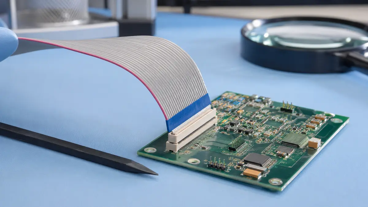
Most ribbon cable damage happens when the connector is misread. A slider, flip bar, locking tab, or friction-fit header can look similar at first glance, but each one releases differently. Pulling a cable while the latch is still engaged can deform the connector contact area, damage the cable stiffener, or create intermittent faults that are difficult to diagnose later.
Engineering note: this guide intentionally avoids unverified pitch, cycle-life, resistance, voltage, or environmental ratings. Those values should be confirmed from the connector drawing, supplier data sheet, and application requirements before repair, replacement, or production approval.
Why Ribbon Cable Disconnection Needs a Controlled Process
Ribbon cables are thin, flexible, and often routed through tight spaces. Their connectors are designed to save board area, which means the release features may be small and easy to damage. A cable can appear to be disconnected cleanly while a contact beam, latch, or stiffener edge has already been stressed.
Common Failure Triggers During Handling
- Pulling from one side of the cable instead of gripping the reinforced end evenly.
- Forcing a locked actuator before the release mechanism has fully moved.
- Mistaking a latch-style connector for a friction-fit connector and prying against the housing.
- Using a metal tool that can scratch contacts, cut insulation, or disturb nearby surface-mount parts.
- Ignoring secondary retention features such as side latches, locking bars, or strain-relief clips.
Why Intermittent Failures Are So Hard to Trace
A damaged ribbon cable connector may still pass a quick functional check. The failure may only appear after the equipment is moved, warmed up, flexed, or placed under normal operating load. That is why post-removal inspection matters. If the cable stiffener is peeling, the contact area is scratched, or the latch no longer closes evenly, the issue should be treated as a connector system problem rather than a simple cable reseat.
How to Remove Ribbon Cable Connections Safely
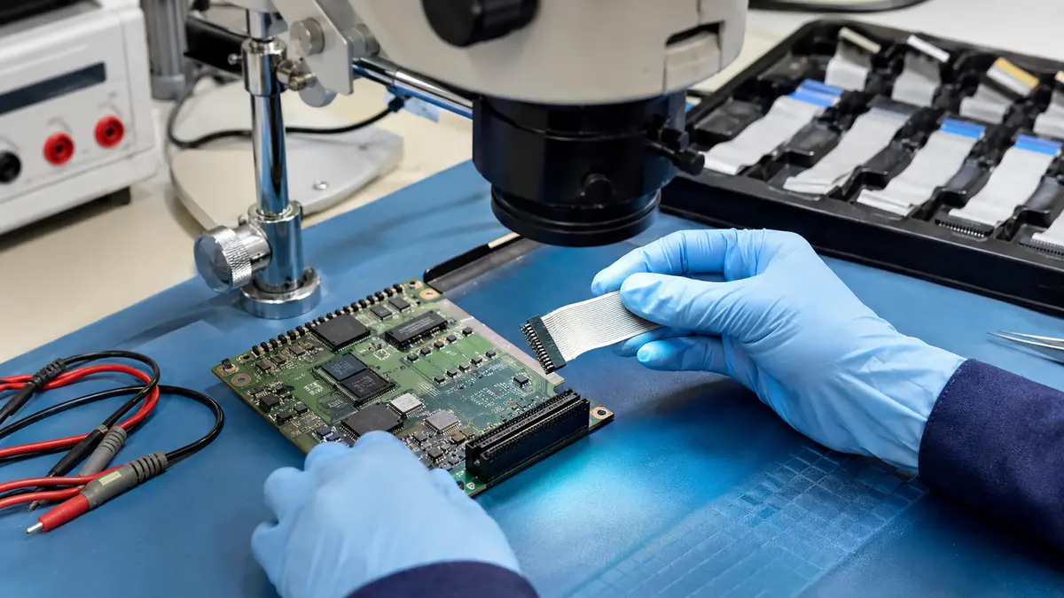
The safest approach is repeatable: prepare the work area, identify the connector, release the retention feature, pull from the correct area, and inspect before reuse. This is also the most reliable way to teach technicians how to remove ribbon cable connections without turning a routine service step into board rework.
Before You Touch the Connector
- Power down the equipment and confirm that stored energy has been discharged according to the product service procedure.
- Use an ESD-safe surface, grounded wrist strap, and clean lighting so the connector mechanism is visible.
- Select a non-marring plastic spudger or wide nylon tool. Avoid sharp metal tweezers near connector contacts.
- Inspect the cable stiffener, latch, solder joints, and nearby components before removal so any existing damage is documented.
- Check whether the cable has a pull tab, reinforced end, strain-relief clip, or separate locking feature.
Step-by-Step Release Procedure
- Identify the connector type before applying force. Look for a slider, hinged bar, side latch, top latch, or absence of any visible actuator.
- Release the retention feature evenly. If the connector uses a slider, move it gently from both sides. If it uses a flip bar, lift the bar evenly instead of twisting one corner.
- Grip the cable only by the stiffener, pull tab, or reinforced end. Do not pull on the flexible conductor body.
- Pull straight out along the connector entry direction with slow, even pressure.
- If the cable resists, stop. Recheck for a hidden latch, side clip, adhesive, routing constraint, or actuator that has not fully released.
- Place the removed cable flat on the ESD-safe surface and avoid kinks, creases, or sharp bends.
Post-Removal Inspection
After removal, examine the cable end and connector before deciding whether the cable can be reused. Look for uneven stiffener edges, lifted conductor traces, scratches in the contact area, cracked actuator plastic, and connector bodies that no longer sit flat on the PCB. For critical assemblies, a visual check should be paired with the product’s normal electrical verification method.
Types of Ribbon Cable Connectors and Release Mechanisms
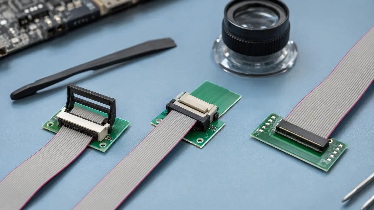
Different connector families require different handling. The table below avoids fixed dimensional claims because exact pitch and part geometry must be confirmed from the component drawing. Use it as a recognition guide, not as a substitute for the connector data sheet.
| Connector Type | How to Recognize It | Release Method | Common Mistake |
|---|---|---|---|
| FFC/FPC ZIF slider | Small side or front slider, often in a contrasting plastic color. | Move the slider evenly to the open position, then remove the cable by the stiffener. | Pulling the cable while the slider is still locked. |
| FFC/FPC flip-lock | Hinged bar across the connector mouth. | Lift the bar gently and evenly, then withdraw the cable straight out. | Lifting one side only and twisting the hinge. |
| Friction-fit ribbon connector | No visible moving latch; retention comes from contact pressure and fit. | Grip the reinforced end and pull straight out without rocking the connector body. | Prying against the PCB-mounted housing. |
| IDC ribbon header | Ribbon cable terminated into a larger connector body, sometimes with strain relief. | Release any clip or strain-relief feature, then pull the connector body evenly. | Rocking the connector side to side and stressing header pins. |
| Locking-tab display cable | Side latch, top latch, or small metal retention feature. | Depress or slide the lock according to its geometry before removing the cable. | Forcing the cable before the secondary lock is free. |
Visual Checklist Before Removal
- Find the actuator or confirm that the connector has no moving part.
- Check for molded arrows, latch seams, side notches, or a small top bar.
- Verify whether the cable end has a reinforced stiffener or pull tab.
- Confirm the cable exits in a direction that allows straight removal.
- Pause if the connector design is unfamiliar, especially on densely populated boards.
How to Replace a Ribbon Cable Connector
If the PCB connector is cracked, heat damaged, contaminated, or no longer provides even retention, replacement may be necessary. How to replace a ribbon cable connector depends on the board design, connector footprint, available tooling, and inspection capability. In a production or repair-depot setting, this should be handled with controlled soldering, magnification, and post-rework verification.
Signs Replacement May Be Required
- The latch no longer closes evenly or does not hold the cable flat.
- The connector housing is cracked, warped, or missing a retention feature.
- Contacts appear bent, contaminated, worn, or no longer aligned with the cable contact area.
- PCB pads or solder joints show movement, lifting, or visible damage.
- The same cable position repeatedly creates intermittent behavior after reseating.
Controlled Replacement Workflow
- Document the original connector orientation, footprint, cable entry direction, and any mechanical keep-out areas.
- Confirm the replacement part against the drawing and application requirements before desoldering the old connector.
- Use controlled rework equipment and suitable board support so the connector lifts only after all solder joints are ready.
- Clean and inspect pads before placing the replacement connector.
- Align the connector to the original footprint and verify cable entry before final soldering.
- Inspect every visible solder joint and test the assembly using the product’s normal electrical and mechanical checks.
For new product development, repeated field replacement is a signal to review the interconnect choice, cable routing, strain relief, and service procedure. LinkManu’s custom cable assemblies can be evaluated as part of a broader connector and cable routing review when a standard cable path is creating recurring handling risk.
How to Repair a Ribbon Cable
How to repair a ribbon cable is not only a question of continuity. A repair that passes a simple electrical check can still fail when the cable is flexed, routed through a chassis, or exposed to vibration. For engineering and procurement decisions, repair should be treated as a temporary evaluation path unless the original performance requirements can be verified.
When a Cable May Be Repairable
- The damage is away from the connector end and does not affect the reinforced insertion area.
- The insulation damage is localized and does not expose adjacent conductors in a way that can short.
- The cable is used only for bench evaluation or non-critical service after documented approval.
- The repair area can be strain relieved and retested under the expected routing condition.
When Replacement Is the Better Engineering Decision
- The stiffener is peeling, cracked, shortened, or no longer enters the connector squarely.
- Multiple conductors are damaged near the connector end.
- The cable carries sensitive, high-density, or timing-critical signals where added repair geometry may affect performance.
- The assembly will be used in a product shipped to customers rather than a controlled bench setup.
Verification After Any Repair
Any repaired cable should be inspected, electrically checked, flexed according to the product’s service expectation, and checked again. If the resistance, signal behavior, or mechanical fit changes after movement, the repair should not be treated as production-ready. When uncertainty remains, a new cable assembly is usually the more defensible choice.
Selection Factors for Ribbon Cable Assembly Projects
For sourcing teams, the repair story often points back to design selection. A cable that is difficult to disconnect, easy to misroute, or repeatedly damaged during inspection may need a different connector, latch style, stiffener design, or strain-relief approach.
| Selection Factor | What to Confirm | Why It Matters |
|---|---|---|
| Connector type | Slider, flip-lock, locking latch, IDC, or friction-fit design. | Release method affects service training, inspection speed, and damage risk. |
| Retention and strain relief | How the cable is held, routed, and protected from pull or bending forces. | Poor strain relief can move stress to the stiffener edge or connector solder joints. |
| Electrical and signal requirements | Required current, voltage, signal speed, shielding, and contact resistance from approved drawings. | These values determine whether a repair, alternate connector, or custom assembly is acceptable. |
| Operating environment | Expected vibration, dust, humidity, service access, and handling frequency. | Environment can drive the need for locking features, routing control, or additional protection. |
| Manufacturing process | Assembly method, inspection plan, tooling, and documentation requirements. | Process control helps keep cable seating, connector alignment, and lot-to-lot consistency visible. |
LinkManu can review cable assembly requirements around assembly, injection molding, stamping, and tooling capabilities when the project needs more than a catalog part. Certification references such as IATF 16949 and ISO 14001 can also be discussed during supplier qualification, but the final requirement should always be matched to the application and customer documentation. For early selection questions, use Get Engineering Review and include the drawing, cable route, connector family, and expected service condition.
Connecting Service Lessons to Cable Assembly Design
A good ribbon cable assembly is not judged only by whether it works on the first build. It should be understandable to service, inspectable after handling, and matched to the product’s mechanical route. If technicians repeatedly ask how to disconnect ribbon cable connections on the same assembly, the project may need clearer documentation, a more robust latch, a different stiffener, or a more controlled cable path.
For designs that need a non-standard retention feature, special housing geometry, or an improved cable-to-connector transition, Custom Connectors may be part of the engineering discussion. For teams still comparing product families, the Products page gives a broader entry point before moving into a specific cable assembly review.
Frequently Asked Questions
How do I disconnect a ribbon cable connector that has no visible latch?
First, inspect the front, sides, and top of the connector for a small slider, flip bar, or side latch. If no actuator exists, it may be a friction-fit connector. In that case, grip the reinforced cable end or connector body and pull straight out with even force. Stop if the cable resists, because a hidden lock or routing constraint may still be present.
Can a ribbon cable be reused after being disconnected?
Yes, but only if the stiffener, contact area, latch engagement, and cable route remain in good condition. Do not reuse a cable with peeling reinforcement, scratched contacts, cracked insulation, or a connector end that no longer seats squarely. Critical assemblies should be checked with the product’s normal verification procedure before reuse.
How to disconnect a ribbon cable on a new motherboard?
Identify the connector style before pulling. Many compact boards use a small flip-lock or slider-style connector. Release the actuator gently with a plastic tool, hold the cable by the reinforced end, and pull straight out. Avoid lifting one side of a latch, pulling on the flexible cable body, or using a metal tool near the contacts.
What four connector features should you consider when selecting a connector?
Confirm the connector type, retention method, electrical requirements, and environmental or mechanical conditions. For ribbon cable assemblies, also check service access and strain relief, because a connector that is hard to release or route can create repeated handling damage even if the electrical rating is correct.
When should I ask for an engineering review instead of repairing the cable?
Ask for review when the same failure repeats, the connector is difficult to identify, the cable carries critical signals, or the application requires documented supplier approval. A review can compare the connector family, cable route, assembly process, and documentation needs before a sourcing or production decision is made.
Send Your Connector Requirement
Share your drawing, BOM, target application, or technical requirements. LinkManu can review connector fit, sample options, documentation needs, and RFQ readiness before final selection.

Technical content reviewed by LinkManu Engineering Team
Prepared by LinkManu Editorial Team for B2B connector engineers, sourcing teams, and product development projects. Updated 2026.