
Board-to-Board Connector Selection
Low Profile Board to Board Connector: A Practical Selection Guide
A low profile board to board connector should be selected from the actual PCB stack-up, not from a generic idea of what “low profile” means. The first review is mechanical: define the board-to-board spacing, component keep-out zones, mating direction, assembly tolerance, and the connector location that the enclosure can accept. Then confirm pitch, pin count, electrical requirements, and supplier evidence against the exact drawing or sample before the design is frozen.
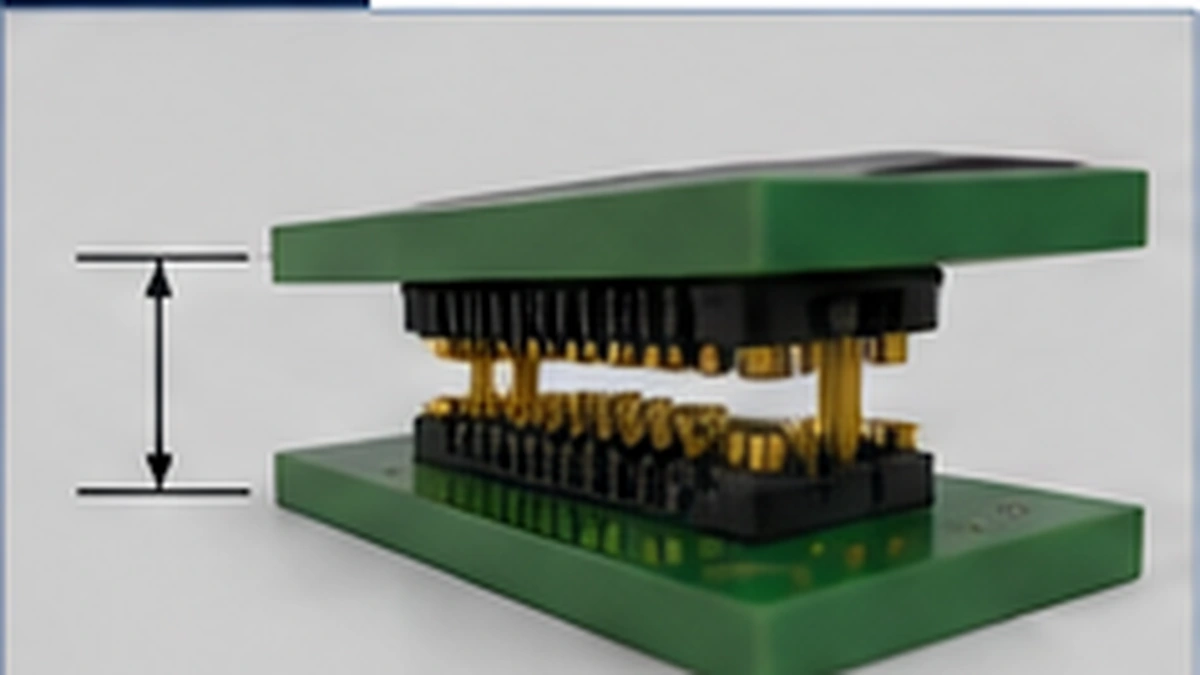
Selection gate: “low profile” is not a universal height threshold. Record the target mating height from the real assembly and verify it against the selected connector drawing, PCB stack-up, and tolerance condition.
Start with the Actual Board-to-Board Height Budget
Vertical space should be defined before the connector family is approved. A connector may look compact in isolation yet still conflict with components, shields, fasteners, or the enclosure once both boards are assembled. Procurement therefore needs the same mechanical inputs as the design team. If the board spacing is still changing, the connector selection should remain provisional.
| Mechanical Input | Decision to Make | Evidence to Keep |
|---|---|---|
| Target board spacing | Define the required mated height from the assembly, not from a catalogue category name. | Controlled mechanical drawing or stack-up model. |
| Component keep-out | Check whether nearby parts, shields, or enclosure features restrict connector position or mating access. | PCB layout and enclosure model. |
| Assembly tolerance | Decide how much positional variation the two boards and mounting hardware can create. | Tolerance stack or assembly drawing. |
| Mating method | Confirm whether the boards are aligned manually, by fixture, or by the product structure. | Assembly process and sample review plan. |
Compare Pitch, Pin Count, and Mating Height as One Decision
Pitch, pin count, and mating height should not be approved independently. Pitch affects how much board area is available around the contact field; pin count affects routing and connector length; mating height controls the final spacing between the two PCBs. The correct values must come from the project drawing, BOM, sample, or approved supplier documentation. Do not transfer a value from another series simply because the connector looks similar.
- Pitch: confirm the exact value required by the footprint and routing plan.
- Pin count: derive it from the schematic and I/O requirement, then check whether the chosen series and footprint support the final arrangement.
- Mating height: compare the selected mated pair with the actual enclosure and board stack-up.
- Orientation: confirm whether the boards mate in the required direction and whether the assembly process can access the connector without forcing the boards out of alignment.
For product-family context, review Board-to-Board Connectors for Compact PCB Interconnects. Treat that page as a starting point for family review; final feasibility still depends on the project drawing, mating height, sample, and application requirements.
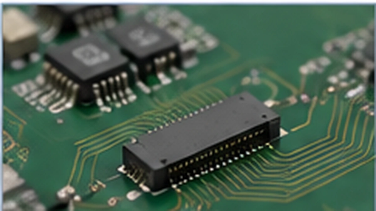
Use Floating or Polarization Features Only When the Assembly Needs Them
If the project requires tolerance absorption or board-mating flexibility, a floating connector can be reviewed as one option. That does not mean a floating mechanism automatically resolves vibration, shock, or every alignment problem. The required movement, board restraint, mating method, and qualification plan still need to be defined for the application. LinkManu’s current product context allows review of Floating Board-to-Board Connectors for projects where tolerance absorption or board-mating flexibility is relevant.
Polarization or anti-misplug features are a separate production decision. Confirm the actual geometry on the selected series and check that it matches the intended assembly sequence. If orientation control is important to manual or automated assembly, make it a drawing requirement rather than assuming every connector in the family provides the same feature.
Procurement check: ask the supplier to identify which alignment, polarization, or floating feature is present on the exact proposed part and how that feature should be verified in the mating assembly.
Turn Electrical and Environmental Requirements into Approval Evidence
The source files do not support publishing universal values for current, voltage, temperature, data rate, mating life, or environmental limits. Those items should remain engineering questions until the exact connector and operating condition are known. A useful RFQ names the requirement and asks for part-specific evidence instead of filling gaps with a “typical” number.
| Requirement | Question for Review | Evidence to Request |
|---|---|---|
| Current carrying requirement | Does the selected contact arrangement support the project load under the intended operating condition? | Part-specific supplier documentation or an agreed project validation plan. |
| Mating durability | How many mate/unmate operations does the application require, and what evidence applies to the selected part? | Drawing, datasheet, test report, or project-specific confirmation. |
| Materials and plating | Which insulator, terminal, plating, and related material requirements are specified by the drawing or end application? | Controlled material specification and supplier confirmation. |
| Environment and qualification | Which mechanical, thermal, electrical, or environmental checks are required for approval? | Agreed test items, methods, limits, and responsibility for the evidence. |
| High-speed signal use | Does the project require signal-integrity review for the connector, footprint, and PCB transition? | Project-dependent simulation or measurement evidence where applicable. |
How LinkManu Can Support a Board-to-Board Project Review
Current company materials describe engineering support that may include Pro-E modeling, Moldflow analysis, ABAQUS terminal stress analysis, and signal-integrity simulation. Which of those steps is relevant depends on the connector design, available input data, and RFQ scope; they should not be assumed to apply to every project.
The same materials list design engineering, mold development, injection molding, post-processing, product assembly, and inspection before shipment as available process steps. Again, the applicable sequence depends on product type and project scope. Testing can also be performed or arranged when required, with some specialized testing outsourced. For a low-profile board-to-board project, the practical supplier question is not “does every project receive every process?” but “which engineering, manufacturing, sample, and validation steps are required for this drawing?”
Prepare the RFQ Before the Connector Is Locked into the PCB
A short, controlled RFQ package is more useful than a long list of assumed specifications. Provide the inputs that let the supplier review fit and feasibility, and mark unknown values as open items.
- Dimensioned drawing or stack-up showing the two PCBs, connector location, mating direction, and target board spacing.
- Required pitch, pin count, and mating height, or a clear indication that one or more of those values still need supplier review.
- PCB keep-out, mounting, and alignment constraints that could affect mating.
- Electrical requirements that must be confirmed for the selected contact arrangement.
- Operating environment and any required mechanical, thermal, electrical, or environmental validation.
- Need for floating, polarization, or other assembly-control features.
- Reference part, sample, or mating component when the project is evaluating an alternative or redesign.
- Sample quantity, documentation needs, and the approval evidence required before BOM release.
Final Selection Gate
Before releasing the BOM, confirm the drawing, pitch, pin count, mating height, PCB stack-up, alignment condition, electrical requirements, environment, sample plan, and supplier evidence. If any of those inputs is still unknown, keep the connector status open instead of approving a low-profile part from appearance or family name alone. That gives engineering and purchasing a clear next step: close the missing drawing or evidence item first.
Frequently Asked Questions
What defines a low profile board to board connector?
It is a board-to-board connector selected to meet a restricted vertical PCB spacing. There is no single universal height threshold; use the target mating height from the actual assembly.
How does pitch affect connector selection?
Pitch changes the contact spacing and PCB footprint. Confirm the required pitch together with pin count, routing, assembly tolerance, and the selected connector drawing.
When should a floating board-to-board connector be reviewed?
Review a floating option when the project needs tolerance absorption or board-mating flexibility. Confirm the required movement and qualification conditions for the actual assembly.
What should I send before requesting a connector review?
Send the drawing or stack-up, pitch and pin requirements, target mating height, PCB constraints, electrical and environmental requirements, and any reference part or sample.
Send Your Connector Requirement
Share the drawing, PCB stack-up, target mating condition, BOM or reference part, electrical requirements, environment, and required approval documents. LinkManu can review the project scope and identify which connector, sample, engineering, manufacturing, and validation questions still need confirmation.

Technical content reviewed by LinkManu Engineering Team
Prepared by LinkManu Editorial Team for B2B connector engineers, sourcing teams, and product development projects.