
High-Speed Connector Engineering Guide
How to Choose High Speed Signal Connectors
Choosing high speed signal connectors starts with the channel, not the catalog. Engineering and sourcing teams need to define the interface, lane assignment, mechanical envelope, operating environment, and evidence required for sample approval before comparing part numbers. A connector that fits the footprint but lacks the right documentation can delay validation even when the first prototype appears to work.
Start with the Interface, Not a Connector Part Number
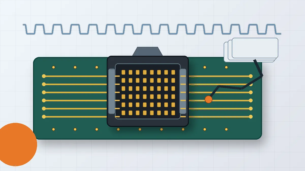
A useful selection review begins with the system architecture. Record the protocol, topology, lane count, board or cable transition, and the point where the connector enters the channel. The main engineering risk is selecting a mechanically convenient connector before the lane map and return path are fixed. That can leave the layout team with an interface that is difficult to route or validate.
The approved high-speed connector product family provides a starting point for board-to-board and cabled projects, but final suitability still depends on the customer drawing, mating height, application requirements, and sample review. Treat family selection as an initial filter rather than proof of electrical performance.
Engineering checkpoint: freeze the lane map, ground allocation, connector orientation, and mechanical keep-out before requesting samples. A supplier cannot review signal-path risk from a part number alone.
Define the Channel Evidence Required for Approval
Ask the design team what evidence will be accepted at each stage. Early concept work may only need drawings and models. Prototype approval may require simulation files, sample measurements, or test reports tied to the intended stack-up. Production release usually needs a controlled drawing, revision status, material and plating requirements, and a clear acceptance plan.
Do not copy impedance, crosstalk, insertion-loss, or data-rate values from an unrelated connector specification. Those values are interface- and construction-specific. Put the project target in the RFQ and ask the supplier to state what can be simulated, measured, or arranged through a test partner.
Convert System Requirements into a Review Matrix
The matrix below keeps electrical, mechanical, environmental, and procurement decisions in one place. It also makes gaps visible before tooling or samples are authorized.
| Decision Area | Information to Submit | Risk if Missing | Expected Supplier Response |
|---|---|---|---|
| Signal path | Protocol, lane map, signal-to-ground assignment, channel constraints | Footprint may route poorly or leave an unclear return path | Feasibility comments and the available SI review method |
| Mechanical interface | Pitch, pin count, mating height, retention, PCB thickness, keep-out | A sample may fit one board revision but fail the assembly tolerance chain | Controlled drawing, footprint, model, and tolerance questions |
| Environment | Temperature exposure, vibration, contamination, cycling, handling | Retention, housing, plating, or test scope may be selected incorrectly | Material and test recommendations that require customer approval |
| Qualification | Sample quantity, measurements, reports, acceptance criteria | Procurement may receive parts without the evidence needed for sign-off | Sample plan, document list, lead-time assumptions, and exclusions |
Mechanical Fit Must Be Reviewed with the PCB Tolerance Chain
Mating height, board spacing, connector orientation, and retention should be checked against the assembled product, not only the nominal CAD position. If the design must absorb PCB assembly tolerance, vibration, or board-to-board misalignment, state that requirement directly. A floating or compliant feature should not be assumed to solve every direction of movement; the drawing must define what movement is expected and what remains fixed.
Separate Power Contacts from High-Speed Review
Some assemblies combine signal, ground, and power contacts. The current requirement, temperature-rise acceptance, and contact grouping need their own review. Do not infer power capability from the signal portion of the connector or from a similar-looking product. Submit the pin assignment and expected loading so the supplier can identify which checks are needed.
Ask for Evidence that Matches the Project Stage
For high speed signal connectors, documentation quality often determines how quickly a project can move from sample to release. A mechanical drawing is necessary, but it is not enough for a channel-sensitive design. The buyer should also ask what simulation inputs are needed, what models can be supplied, what measurements are available, and which tests must be outsourced.
- Before sample approval: confirm the drawing revision, footprint, mating interface, retention method, and material or plating requirements.
- For signal review: define the customer stack-up, channel target, lane assignment, and the evidence expected from simulation or measurement.
- For environmental review: list the actual application conditions and acceptance criteria instead of requesting a broad “industrial” or “automotive” grade.
- For procurement: separate standard parts, modified parts, and new tooling so quotation assumptions are visible.
A useful supplier response should distinguish confirmed capability from items that still require drawing review, sample testing, or external laboratory support. Statements such as “high speed capable” are not an acceptance document.
Review Manufacturing and Engineering Scope
Supplier evaluation should cover more than the connector datasheet. The uploaded company facts list tooling, stamping, injection molding, and assembly capabilities, along with project-dependent engineering support such as Pro-E modeling, Moldflow analysis, ABAQUS terminal stress analysis, and SI simulation. The practical procurement question is which of these steps apply to the specific connector and which evidence will be delivered with the sample.
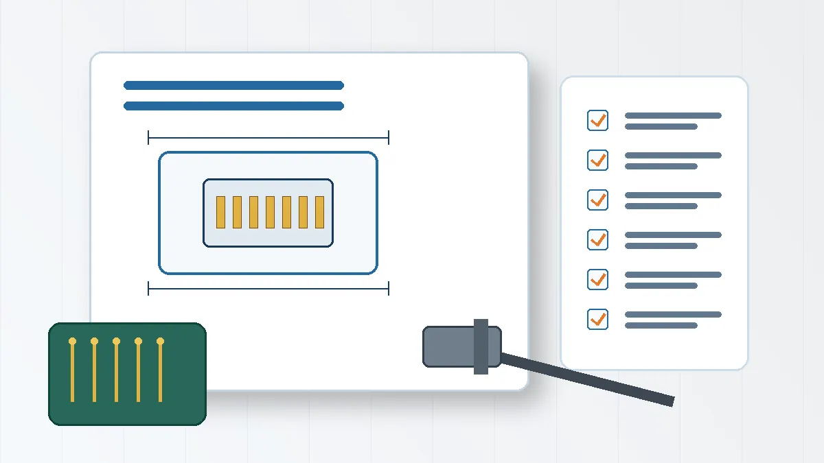
Use the broader LinkManu product overview only to identify relevant product categories. Final process scope should be confirmed against the requested design. If certificates are part of the sourcing requirement, request current copies and check the company name, site, validity period, and scope rather than treating a certification reference as product approval.
Procurement checkpoint: ask who owns the drawing, who controls tooling changes, which tests are performed internally, which may be arranged externally, and how revision changes are approved before production.
Prepare a Ready-to-Review RFQ Package
A complete RFQ reduces back-and-forth and makes quotations easier to compare. At minimum, submit the following:
- A mechanical drawing or marked interface sketch showing pitch, pin count, mating height, orientation, retention, and PCB constraints.
- A pin-out or BOM showing differential pairs, grounds, power contacts, and any reserved positions.
- The protocol and channel context, including the expected PCB or cable transition and the required validation evidence.
- Application conditions, material or plating requirements, flame-rating requirements, and the test items that must be quoted.
- Sample quantity, target schedule, documentation list, and the decision criteria for moving to the next stage.
When comparing quotations, check exclusions as carefully as price. One supplier may include tooling review, models, and test coordination while another quotes only the molded and stamped parts. Those offers are not equivalent until the engineering scope is aligned.
Frequently Asked Questions
What makes a connector suitable for high-speed signals?
Suitability depends on the complete signal path, including pair geometry, return path, shielding, PCB launch, mating interface, and validation evidence. A catalog label alone is not enough.
When should SI data be requested?
Request it before final sample approval when the connector is part of a channel-sensitive interface. Define the stack-up, lane assignment, and acceptance target first.
Which files should be included in the RFQ?
Include the drawing, footprint or model, pin-out, protocol context, environment, test requirements, sample plan, and required reports.
How should supplier SI capability be checked?
Ask which simulation inputs are required, what models or reports are delivered, what equipment is available, and which measurements are handled by test partners.
Final Selection Check
Before releasing a connector for sampling, confirm the drawing, pitch, pin count, mating height, lane and ground assignment, environment, material and plating requirements, validation evidence, sample plan, and supplier process scope. Any open item should be listed as an RFQ question rather than filled with an assumption. That review gives engineering and procurement a common basis for selecting high speed signal connectors and comparing supplier responses.
Send Your Connector Requirement
Share the drawing, pin-out or BOM, target application, mechanical constraints, and required test documentation for a project-specific feasibility review.

Technical content reviewed by LinkManu Engineering Team
Prepared by LinkManu Editorial Team for B2B connector engineers, sourcing teams, and product development projects. Updated 2026.