
Industrial Connector Engineering Guide
4 Pin M12 Pinout for Industrial Connector Selection
A 4 pin M12 pinout is useful only when it is tied to the exact device, connector drawing, and cable assembly being purchased. Matching the connector family and pin count does not, by itself, prove that the electrical assignment is correct. For engineering and sourcing teams, the safer workflow is to treat the pinout as a controlled interface: identify the mating parts, confirm the drawing view, map every conductor to a numbered contact, and keep that approved mapping with the BOM.
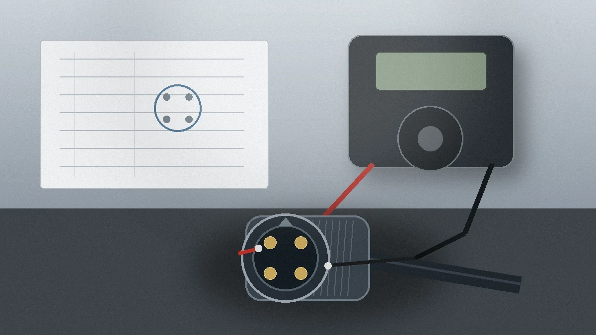
Hypothetical engineering scenario: a replacement cable mates mechanically with the equipment, but the machine still reports an I/O fault. Before treating the sensor or controller as defective, the team compares the device pin assignment with the cable drawing and finds that the ordered assembly does not match the intended electrical map. The lesson is not that one pinout is “correct” for every M12 application; it is that the exact interface must be documented before purchase and checked again before power-up.
Start With the Interface Definition, Not a Generic Diagram
Search results often encourage buyers to look for one universal diagram. That is a poor purchasing specification. The engineering question is narrower: what pin assignment does this exact device revision expect, and what cable assembly reproduces that assignment at the mating interface? If the answer is not available in the device documentation, drawing, approved sample, or supplier documentation, the RFQ is not ready for release.
Before comparing suppliers, capture the interface in a short controlled record. The minimum useful record is the device part number and revision, connector coding shown by the device documentation, connector gender and viewing direction, numbered contact assignment, conductor mapping, cable construction requirements, electrical requirements that still need confirmation, and the environmental conditions that affect the assembly. These items turn “M12 4-pin cable” from a vague description into an engineering requirement.
| RFQ field | What engineering should confirm | Why procurement needs it |
|---|---|---|
| Device identity | Exact equipment part number and revision tied to the pin assignment | Prevents a generic replacement description from overriding the equipment documentation |
| Connector coding | Coding designation shown in the device or mating-interface documentation | Lets the supplier screen mechanical compatibility before quoting |
| Drawing orientation | Whether each pin diagram is shown from the mating face, wiring side, or another stated view | Reduces the risk of comparing two drawings from different viewpoints |
| Pin-to-conductor map | Numbered contacts traced to the required cable conductors or terminals | Creates an auditable electrical pathway instead of relying on color alone |
| Cable and termination | Length, conductor count, termination method, shielding or strain-relief needs, and any field-assembly constraints | Defines what is actually being purchased, not only the connector shell |
| Application conditions | Electrical load, installation environment, motion, ingress exposure, and documentation or test requirements that must be confirmed for the project | Keeps unsupported catalog assumptions out of the purchase order |
Verify the 4 Pin M12 Pinout in a Controlled Sequence
1. Lock the drawing view before comparing pin numbers
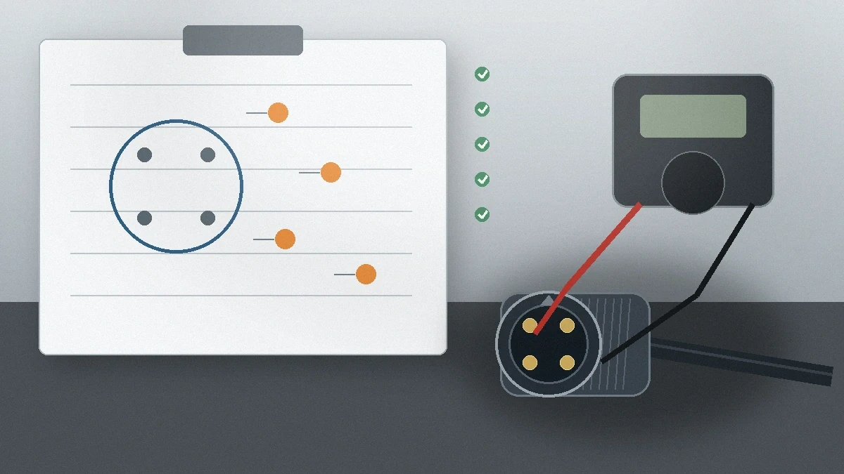
Two drawings can look similar while being presented from different sides of the connector. Do not transfer a pin number from one document to another until the viewing direction is identified on both. A practical review mark-up can place the device drawing and cable drawing side by side, circle the orientation note, and then trace each numbered contact across the interface. If the orientation is unclear, ask the device or cable supplier to clarify it rather than filling the gap from memory.
2. Treat conductor color as an identifier, not proof of function
Color is convenient during assembly and troubleshooting, but a sourcing decision should be based on the numbered pin assignment in the approved documentation. The purchase drawing should state which conductor reaches each numbered contact. That mapping can then be checked on a sample with a continuity tester before the assembly is connected to live equipment. The acceptance criterion is simple: the measured path must match the approved drawing.
3. Separate known requirements from values that still need confirmation
The current evidence set for this article does not support publishing universal current, voltage, temperature, ingress, data-rate, or conductor-size values for a 4-pin M12 assembly. Those belong in the RFQ as confirmation items. Engineering should ask which electrical limits apply to the exact connector and cable, what environmental protection the installation requires, and which drawing or test document will be used for approval. This keeps a selection guide from silently turning a third-party reference value into a LinkManu product claim.
4. Add a pre-power continuity check where the project risk justifies it
For a new cable variant, a changed supplier, or a revised BOM, a continuity check provides a direct way to compare the physical assembly with the approved map. Record the sample or assembly identifier, check the intended end-to-end paths, and investigate any unexpected connection before the cable is energized. The check does not replace equipment documentation or project-specific electrical testing; it confirms that the assembly you received matches the pin map you approved.
Build the Purchase Specification Around the Application
Pinout verification is only one part of connector selection. The assembly also has to fit the equipment, cable route, maintenance method, and operating environment. Instead of inserting unverified catalog values, put the unanswered conditions directly into the sourcing package. Ask which mating interface is required, whether the cable is fixed or moves in service, what sealing or contamination exposure must be addressed, whether shielding or strain relief is needed, and which electrical ratings must be documented for the actual part.
The termination method deserves the same treatment. A factory-assembled cable, panel connection, or field-terminated connector creates different documentation and installation needs. Procurement should not choose among them by description alone. Engineering should define where the connection is made, who will assemble or service it, what drawing must be returned for approval, and what sample checks are required before the part becomes a repeat-order item.
Decision rule: if the BOM line can be interpreted in more than one electrically different way, it is not complete. Add the drawing, coding designation, contact map, cable details, application conditions, and required approval documentation before asking purchasing to source an alternative.
A Procurement Checklist Before the RFQ Is Released
| Check | Release condition |
|---|---|
| Exact device and revision identified | The pin assignment can be traced to the equipment documentation being used for the project |
| Connector coding confirmed | The coding requirement comes from the device or mating-interface documentation |
| Drawing view confirmed | The pin numbering orientation is stated clearly enough to compare the mating parts |
| Pin-to-conductor map attached | The supplier can return a drawing that shows the requested electrical pathway |
| Cable and termination defined | The RFQ states the construction and installation information needed to quote the assembly |
| Application limits listed for confirmation | Electrical and environmental values are requested from project-specific documentation rather than copied from a generic guide |
| Sample approval method defined | The team knows which drawing, continuity check, dimensional review, or other agreed evidence is needed before production approval |
| Revision control assigned | Repeat orders will reference the approved drawing or part revision instead of a free-text connector description |
How LinkManu Can Support the Engineering Review
LinkManu’s current company materials support a cautious, project-dependent engineering role rather than a universal M12 compatibility claim. Project support can include design and engineering review before tooling and production, depending on the RFQ scope. For molded connector components where that review is applicable, the company materials describe tools such as Pro-E modeling and Moldflow analysis; these steps should not be assumed for every project. The broader Engineering & Quality page is the appropriate internal reference for this capability context.
Testing and verification should also be written as project requirements, not automatic deliverables. Current company materials state that quality checks may include insertion and extraction force testing when required, and that hi-pot or other relevant testing may be included or arranged according to the project. Some testing can be outsourced when required. If a test matters to approval, name it in the RFQ and request the corresponding evidence rather than assuming it is part of a standard connector package.
For industrial-equipment applications, use the Industrial Equipment Connector Solutions page as the required topic-cluster reference. If the project needs a custom connector or cable review, Custom Connector Support provides the relevant project-entry point. The useful first submission is not a generic “4-pin M12” request; it is the drawing, BOM, device interface information, application conditions, and the questions engineering still needs to close.
What to Send for a Connector Review
Before asking for a quote, assemble the information that prevents interpretation. Send the device or mating-interface drawing, the required contact assignment, connector coding, cable and termination requirements, installation environment, and any electrical or test documentation that must be confirmed. If a sample already exists, identify its revision and explain whether the goal is reproduction, modification, or evaluation of another configuration. Do not describe an alternative as compatible until the mating and electrical requirements have been reviewed.
If some requirements are still unknown, mark them as open questions. That is safer than filling them with a value copied from a generic M12 reference. A complete RFQ distinguishes what is fixed by the equipment, what can be proposed by the supplier, and what must be verified on a sample. For a general project inquiry, use Contact LinkManu.
Frequently Asked Questions
Is there one universal 4 pin M12 pinout?
Do not treat a generic diagram as universal. Use the exact device documentation and the approved cable or connector drawing to confirm the numbered contact assignment for the project.
Can wire color be used to identify each pin function?
Color can help identify conductors, but the purchase specification should map numbered contacts to conductors from the approved drawing. Verify the physical path on a sample when needed.
What should an RFQ include for a 4-pin M12 cable or connector?
Include the device or mating-interface drawing, coding requirement, contact map, cable and termination details, application conditions, and the electrical or test values that must be confirmed for the exact part.
Can LinkManu confirm compatibility from “M12 4-pin male” alone?
No universal compatibility should be inferred from that description. A project review needs enough drawing, sample, BOM, and application information to evaluate the required interface and documentation.
Send Your Connector Requirement
Share the drawing, BOM, mating-interface information, target application, and open verification questions. The review scope can then be defined against the actual project rather than a generic pinout assumption.

Technical content reviewed by LinkManu Engineering Team
Prepared by LinkManu Editorial Team for B2B connector engineers, sourcing teams, and product development projects.