
Engineering Selection Guide
Selecting High Speed Fine Pitch Connectors
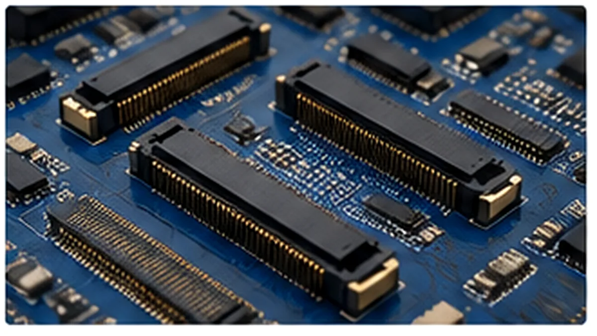
High speed fine pitch connectors should be selected from the complete channel and mechanical stack-up, not from pitch or pin count alone. The connector footprint, via field, return-path arrangement, mating height, enclosure tolerance, and available supplier data all affect whether a candidate is practical. Before approving a part, engineering and purchasing teams should agree on what must be confirmed by drawing, model, sample, or test report.
Start With the Channel, Not the Connector Catalog
A PCB simulation can look acceptable while the physical interconnect remains uncertain. Pads, vias, connector contacts, dielectric regions, and the mated interface introduce discontinuities that are not represented when the connector is treated as an ideal connection. The engineering decision is therefore not simply whether a connector is described as “high speed,” but whether its supporting data can be applied to the actual board layout.
Layout gate: Do not freeze the footprint until the connector launch, anti-pad geometry, ground assignment, and via strategy have been reviewed with the channel model or an equivalent validation plan.
Begin with the protocol, lane count, channel topology, equalization assumptions, and the loss, reflection, crosstalk, and skew limits assigned to the connector transition. Those limits should come from the applicable system specification and the project link budget. When the connector allocation is not defined, ask the system owner to confirm it rather than selecting a part from a headline performance label.
The LinkManu overview of high-speed connectors for PCIe, SAS, and board-to-board signal links provides the relevant product-family context. The project still needs part-specific confirmation because a connector family page cannot replace a drawing, footprint review, or test document for the proposed configuration.
Translate System Requirements Into Connector Checks
A useful comparison sheet separates requirements that can be verified from items that remain assumptions. This prevents purchasing teams from comparing two candidates only by unit price or nominal pitch while engineering is still missing the data needed for approval.
| Selection area | Engineering judgment | Evidence to request |
|---|---|---|
| Protocol and lane plan | Confirm how many signal pairs, grounds, shields, and power contacts are required. | Pin assignment, application drawing, and the system interface requirement. |
| Pitch and escape routing | Check whether the PCB fabricator and assembly process can support the fan-out without creating an avoidable yield or rework risk. | Recommended footprint, PCB capability feedback, and assembly review. |
| Signal integrity | Evaluate the connector and footprint together; a connector-only result may not represent the installed interface. | Touchstone files, S-parameters, fixture details, or a suitable simulation model. |
| Mating geometry | Confirm board spacing, mating height, alignment allowance, and full engagement in the enclosure. | 2D drawing, 3D model, tolerance stack, and mating-part definition. |
| Mechanical retention | Review how vibration, handling, cable load, or board movement could reach the contacts or solder joints. | Retention features, mounting details, and the project mechanical test plan. |
| Environment and life | Do not assume a catalog part covers the operating environment or required mating cycles. | Application limits and part-specific qualification or test documentation. |
Pitch is one constraint within this matrix. A smaller pitch may reduce board area, but it can also tighten routing, soldering, coplanarity, inspection, and repair margins. The practical choice is the smallest interface that the PCB, assembly, enclosure, and validation plan can support with acceptable risk—not the smallest option shown in a catalog.
Check Mechanical Stack-Up Before Electrical Approval
Mating height and board spacing should be reviewed against the enclosure and both PCB drawings. A nominal match is not enough when component height, board bow, assembly tolerance, and alignment features consume the available margin. If the connector is expected to absorb board-to-board misalignment or vibration, that requirement should be stated in the RFQ and verified against the proposed contact and housing design.
Also confirm whether the interface needs polarization, latching, hold-down features, guide posts, or a defined insertion and extraction method. These details affect handling and assembly even when they do not appear in the electrical link budget. A connector that is electrically promising but difficult to align or fully seat can create an avoidable production-control problem.
Review the footprint as part of the mechanical design
The footprint controls more than routing. Pad dimensions, solder-mask strategy, via placement, component keep-outs, inspection access, and rework clearance should be checked with the assembly process. When the connector uses multiple rows or a dense ground pattern, ask whether the proposed inspection method can verify the joints that are not visually accessible.
Request Data That Matches the Installed Interface
Datasheets often provide mechanical dimensions and basic electrical ratings but may not include the high-frequency information needed for a channel review. When S-parameter data is available, check the fixture, reference planes, de-embedding method, mating condition, and footprint assumptions. Data from a standard test board should not be treated as proof that a different stack-up and launch will produce the same result.
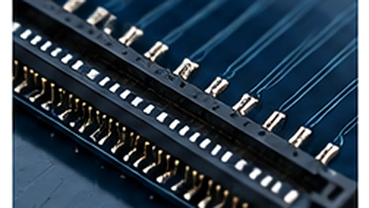
Where suitable models are unavailable, define a project-specific simulation or test plan before tooling or production release. LinkManu company materials describe engineering support that may include Pro-E modeling, Moldflow analysis, terminal stress analysis, and signal-integrity simulation, depending on project scope. Availability and deliverables should be confirmed for the proposed connector rather than assumed for every RFQ.
Data review checklist: request the connector drawing, mating-part definition, recommended PCB footprint, model or measured data, fixture information, applicable test reports, and revision status. Record any missing item as an open approval condition.
Qualify the Supplier Around the Proposed Part
Supplier evaluation should focus on process control and evidence for the specific design. Ask how tooling, stamping, injection molding, assembly, and inspection would apply to the part under review. The listed manufacturing process may differ by connector type and RFQ scope, so capability statements should be followed by questions about ownership of tooling, critical dimensions, inspection points, and outsourced testing.
For high-speed projects, also ask who controls the electrical model, how design revisions are documented, and whether sample results can be linked to the same drawing revision proposed for production. A generic quality certificate or factory presentation does not establish the performance of an individual connector. Part-specific drawings, samples, and test evidence remain the approval basis.
Use samples to close defined risks
A sample request is most useful when it answers a written question. Examples include mating fit, board spacing, alignment, assembly access, footprint feasibility, contact engagement, or a planned electrical measurement. Without a defined acceptance check, a sample can confirm appearance while leaving the main engineering uncertainty unresolved.
Prepare an RFQ That Can Be Reviewed Efficiently
Send enough information for the supplier to distinguish a standard selection request from a modified or custom design. At minimum, include the connector family, pitch requirement, pin count, mating height, board spacing, target application, protocol, environmental conditions, expected mating use, and required documentation. Attach the PCB or enclosure drawing when the connector must fit an existing stack-up.
State whether the project needs a compatible alternative, a modified interface, or a new design. Do not describe a candidate as a drop-in replacement until the mating interface, footprint, electrical requirements, materials, and validation evidence have been compared. Compatibility is a project conclusion, not a catalog assumption.
The final release decision should identify what has been confirmed and what remains open. Before issuing a purchase order, verify the approved drawing revision, pitch, pin assignment, mating height, current requirements, operating environment, test documentation, sample status, and supplier capability for the agreed scope. The broader LinkManu product range can help place the request in the correct connector family, but the RFQ should still describe the exact interface under review.
Frequently Asked Questions
What is an SFF connector?
It is a connector interface associated with a Small Form Factor specification. Confirm the exact SFF document and revision because the term covers multiple interfaces.
What is the Small Form Factor Committee?
It is the industry group behind SFF interoperability specifications and now operates within SNIA. Use the current specification directory to verify document status and revision.
Is a smaller pitch always better?
No. Smaller pitch can save board area, but routing, assembly tolerance, inspection, and rework capability may become the limiting factors.
What should be requested when a datasheet lacks SI data?
Ask for applicable S-parameters or a model, fixture details, the recommended footprint, and a plan for simulation or measurement in the project stack-up.
Send Your Connector Requirement
Share the drawing, PCB stack-up, mating-height requirement, protocol, environment, and documentation needs. LinkManu can review connector fit, sample scope, open engineering questions, and RFQ readiness before final selection.

Technical content reviewed by LinkManu Engineering Team
Prepared by LinkManu Editorial Team for B2B connector engineers, sourcing teams, and product development projects.