
Fiber I/O Selection Guide
Types of Fiber Connectors Chart for Industrial I/O
A useful types of fiber connectors chart should do more than name LC, SC, FC, MPO, and ruggedized formats. For an enclosure or external I/O interface, the real decision includes panel fit, cable exit, cleaning access, optical compatibility, and the way technicians will handle the connection after installation. The chart below is a shortlist tool. Final selection still needs a drawing, the optical system requirements, and supplier documentation.
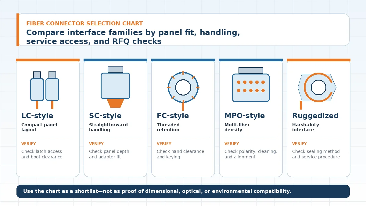
Engineering limit: connector names are not proof of interchangeability. Confirm the exact adapter, keying, polish, fiber mode, panel opening, and termination method from the project drawing and the selected supplier’s documentation.
Types of Fiber Connectors Chart: What Each Family Changes
Start with the interface family, then test it against the installation. The same family name can cover different housings, adapters, boots, and panel-mount arrangements. Procurement should therefore compare the complete assembly rather than approve a substitute from the connector label alone.
| Connector family | Why it may enter the shortlist | Main project risk | What to confirm before approval |
|---|---|---|---|
| LC-style small-form interface | Useful where panel density and compact cable routing matter. | A dense layout can leave too little room to release the latch, clean the end face, or route the boot without side load. | Adapter type, latch access, duplex arrangement, rear clearance, boot direction, and the exact panel cutout. |
| SC-style push-pull interface | Often considered where technicians need a clearly handled simplex or duplex connection. | The larger body and push-pull action may conflict with a crowded panel or nearby controls. | Panel depth, adapter retention, hand clearance, dust-cap access, cleaning procedure, and mating orientation. |
| ST-style bayonet interface | May appear in existing equipment or maintenance-driven replacement work. | A legacy interface can create sourcing and compatibility problems when the installed adapter, tool, or cable construction is unclear. | Installed mating interface, keying, termination tooling, replacement strategy, and whether the project should preserve or redesign the legacy connection. |
| FC-style threaded interface | Considered when a threaded coupling is preferred for controlled retention. | Thread access and service time can become constraints in a recessed or tightly spaced panel. | Thread and keying details, hand clearance, cable rotation risk, adapter mounting, and the supplier’s mating instructions. |
| MPO-style multi-fiber interface | Relevant to multi-fiber links and high-density channel planning. | Polarity, alignment, cleaning, and transceiver mapping are system decisions; a mechanical fit alone is not enough. | Fiber count, polarity method, pin configuration, key orientation, adapter footprint, inspection method, and channel mapping. |
| Ruggedized or expanded-beam variant | May suit an exposed or contamination-prone service point when the system design calls for a protected interface. | Ruggedized designs are supplier-specific. Similar-looking parts may use different sealing, cleaning, or mating systems. | Sealing concept, materials, cleaning process, mating compatibility, cable construction, and the exact environmental test documentation required by the project. |
For context on the surrounding panel and external-interface choices, review I/O Connectors for External and Panel Interface Projects. The fiber interface should be coordinated with the enclosure, cable routing, adjacent copper connectors, and the equipment service plan rather than selected as an isolated component.
Start with the Panel and Service Conditions
Before comparing product drawings, define where the connector sits and who will touch it. An interface inside a protected cabinet has a different risk profile from one exposed at an outdoor access panel. The supplier cannot evaluate this from a connector name alone.
- Panel geometry: provide the cutout, wall thickness, available rear depth, nearby components, and the permitted cable exit direction.
- Service access: state whether technicians can see the interface, use both hands, remove a dust cap, and clean the end face without dismantling the enclosure.
- Operating exposure: describe dust, moisture, cleaning agents, vibration, handling frequency, and storage conditions. Convert these into project-specific acceptance checks rather than copying a generic rating.
- Cable management: show the clamp or strain-relief location and the route to the next fixed point. A correct adapter can still fail the installation review when the boot or cable is forced into an unsuitable path.
The procurement judgment is simple: reject a quotation that confirms only the connector family but does not address the panel-mount assembly, cable construction, and service method shown on the drawing.
Lock the Optical Decisions Before Requesting Samples
Fiber mode, polish, channel arrangement, and transceiver compatibility belong to the system design. They should be frozen before the mechanical connector choice is released for tooling or panel fabrication. A visual match between two plugs does not confirm optical compatibility.
Ask the system owner to define the acceptable optical budget and the required verification method. Then request a sample built with the final cable, termination, adapter, and mating interface. Testing only a loose connector on the bench can miss problems created by panel alignment, cable loading, contamination, or the production cleaning process.
Do not copy exact values from a generic chart. Ferrule dimensions, loss targets, environmental ratings, and mating-life requirements should come from the approved drawing, supplier datasheet, sample evaluation, or an agreed test plan.
Mechanical Fit Is Often the Procurement Bottleneck
The drawing review should cover the adapter, flange, latch or coupling mechanism, boot, cable exit, and technician hand clearance as one interface. A change to any of these items can affect the enclosure cutout, assembly sequence, or field replacement procedure.
Where the project requires a modified surrounding housing or panel feature, the uploaded company materials list tooling, injection molding, and assembly among available manufacturing capabilities. Scope still needs confirmation: the supplier may be reviewing the panel interface or housing while the optical ferrule, adapter, and termination remain controlled by another approved source. State this boundary in the RFQ to avoid an assumed responsibility gap.
Projects that combine fiber with copper I/O should also review the broader LinkManu product categories so that connector spacing, fastening, cable routing, and assembly access are checked together.
Build an RFQ That Can Be Reviewed Without Guesswork
A concise RFQ package is more useful than a long email with no drawing control. The buyer should make every unverified item visible so the supplier can answer, request evidence, or mark the point for sample validation.
| RFQ category | Information to provide | Approval question |
|---|---|---|
| Application and environment | Equipment type, panel location, exposure, handling frequency, and service constraints. | Has the proposed interface been reviewed against the actual operating condition rather than a generic indoor assumption? |
| Mechanical definition | Controlled drawing, cutout, wall thickness, rear clearance, cable exit, and adjacent components. | Does the quotation identify the exact adapter, mounting method, and mating interface? |
| Optical definition | Fiber mode, polish, channel plan, transceiver information, and project acceptance criteria. | Which items are confirmed by documentation, and which still require sample testing? |
| Cable and termination | Cable construction, length control, strain relief, field or factory termination, and cleaning method. | Is the quoted sample representative of the production cable assembly? |
| Evidence and change control | Required datasheets, drawings, inspection records, test documents, and revision approval process. | Can every critical claim be traced to an approved document or agreed verification step? |
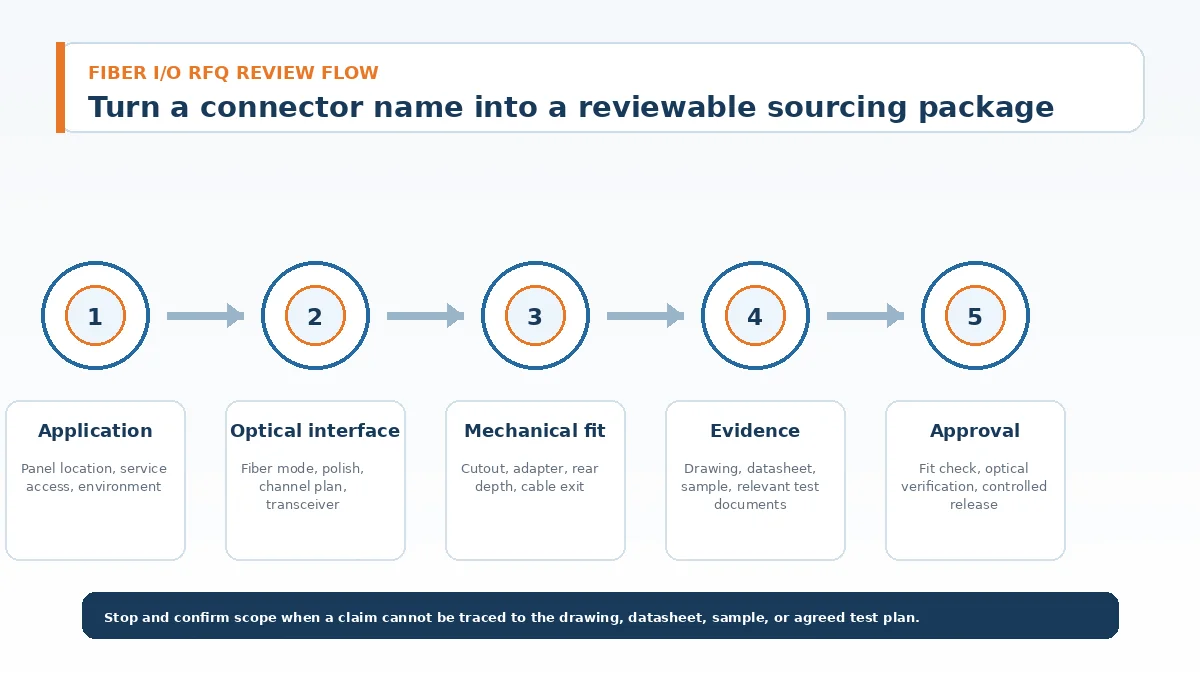
- Send the controlled drawing, application description, and optical interface requirements.
- Ask the supplier to separate confirmed items from assumptions and open questions.
- Review the proposed sample configuration before it is built, including cable, adapter, boot, and termination details.
- Evaluate fit, cleaning access, mating operation, and optical performance in the actual panel or a representative fixture.
- Release the approved drawing and evidence package before volume purchasing. Any later connector, adapter, cable, or termination change should return to review.
For a project-specific review, use Contact Engineering Support and include the drawing revision, target application, sample quantity, and the technical points that remain open.
Fiber Connector Selection FAQ
What are the main types of fiber connectors?
Common families include LC, SC, ST, FC, MPO-style multi-fiber interfaces, and ruggedized variants. The correct choice depends on the exact mating adapter, optical system, panel design, and service conditions.
Are there exactly seven standard fiber connector types?
No. Lists vary by application and may mix common, legacy, and specialty formats. Use the project drawing and equipment interface to define the required family.
Can connector size be selected from an online chart?
Only for an initial shortlist. Final dimensions must be checked against the supplier drawing, adapter, panel cutout, cable boot, and available service clearance.
What should be verified first when comparing two suppliers?
Verify the exact mating interface, polish and fiber mode, panel-mount dimensions, cable construction, termination process, and the documents supplied with the sample.
Send Your Connector Requirement
Share the controlled drawing, application conditions, optical interface requirements, and open verification points. The review can then focus on fit, sample scope, documentation, and the items that must be confirmed before release.

Technical content reviewed by LinkManu Engineering Team
Prepared by LinkManu Editorial Team for B2B connector engineers, sourcing teams, and product development projects.