
Connector Engineering Guide
M8 4-Pin Connector Pinout & Selection Guide
The M8 4-Pin Connector Pinout & Selection Guide is best used as a project-review sequence, not a universal wiring chart. Four contacts still leave several decisions open: viewing direction, coding, device-side function, cable construction, board termination, enclosure clearance, and supporting documentation. Start with the approved device drawing and datasheet rather than a familiar cable or an old schematic.
Scope limit: This guide does not assign universal pin functions, ratings, materials, or environmental grades. Confirm those items against the customer drawing, device datasheet, sample, and supplier documentation for the specific project.
Start With the Viewing Direction, Not the Wire Color
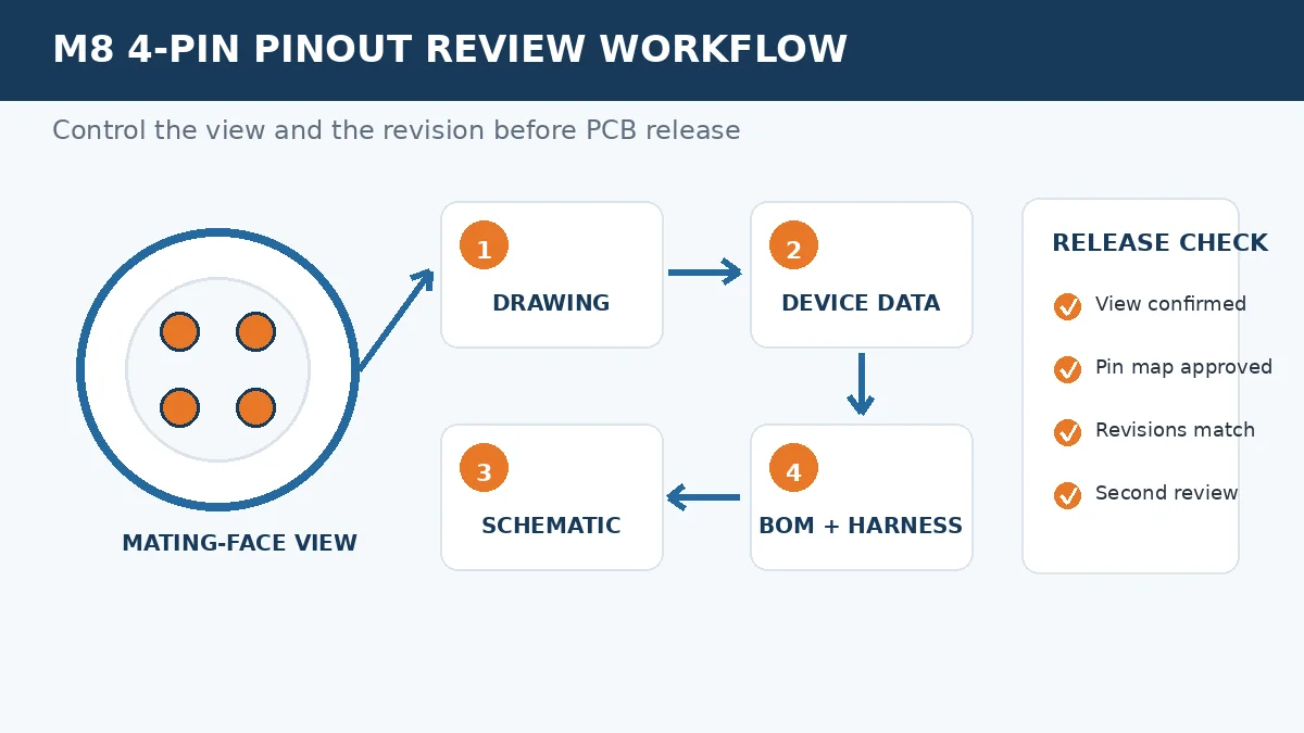
The first engineering check is orientation. A pin-side view and a cable-side view can appear mirrored, and male and female drawings may use different reference directions. Copying a color sequence without confirming the view can place supply, return, or signal functions on the wrong board circuit. The release criterion should be an approved pin-to-signal table tied to a drawing revision.
- Identify whether the drawing shows the mating face, termination side, male side, or female side.
- Match the physical contact numbers to the end-device functional assignments.
- Confirm the required coding or keying from the device specification; do not infer it from “4-pin.”
- Record signal name, wire identification, and destination circuit in the schematic and harness documentation.
- Have a second reviewer compare the drawing, schematic, BOM, and assembly instruction before PCB release.
A wire color can support assembly control, but it is not the primary engineering authority. Cable suppliers may use different conventions, and a replacement cable can preserve the connector shape while changing the internal assignment. Procurement should therefore request the exact cable drawing and revision, not only a product photo or contact count.
Turn the Pinout Into a Controlled Project Document
A usable pinout package connects electrical intent to physical orientation. It should also show who owns each confirmation. Without that control, a correct schematic can still be assembled with the wrong cable view or an outdated drawing.
| Review Item | What Must Be Confirmed | Release Condition |
|---|---|---|
| Connector drawing | Mating view, contact numbering, coding or keying, mounting orientation | Drawing revision referenced in the BOM |
| Device assignment | Function of every contact and any unused position | Pin-to-signal table approved by the electrical owner |
| Cable or harness | Wire identification, conductor requirements, shielding, length, and test scope | Harness drawing matches the schematic and sample |
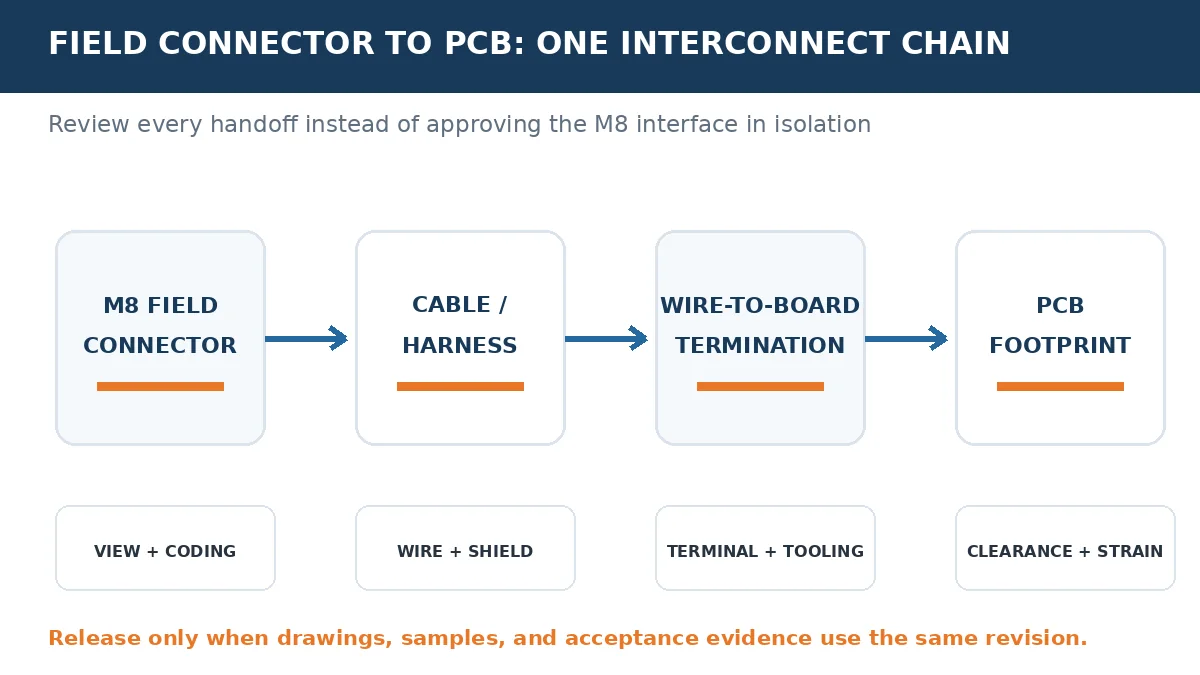
| PCB interface | Board connector, terminal, footprint, polarity control, and cable exit | Mechanical and electrical reviews use the same revision |
Coding and keying help control mechanical mating, but they do not replace electrical verification. The project still needs the device assignment and internal cable routing. Treat any coding label from a supplier page as a question to confirm against the approved device documentation.
Review the Board-Side Termination as a Separate Design Decision
The M8 interface is only the field side of the connection. The cable may terminate through a crimp contact, soldered connection, IDC arrangement, or another project-specific method before reaching the PCB. Each option changes tooling, inspection, repairability, strain relief, and board-space requirements. Review the available wire-to-board connector families for PCB-to-wire interfaces only after the wire and assembly requirements are defined.
| Design Factor | Engineering Decision | Risk if Left Open |
|---|---|---|
| Termination method | Confirm the assembly process, tooling, inspection access, and repair plan | A selected housing may not fit the intended production workflow |
| Wire and terminal fit | Confirm conductor, insulation, terminal, and housing requirements per project | Poor retention or an uninspectable crimp may reach assembly |
| PCB footprint | Check pitch family, orientation, polarization, and keep-out area | The cable exit can interfere with components or enclosure walls |
| Mechanical loading | Decide how strain is transferred away from the solder joint or terminal | Vibration or service handling may load the board connection |
LinkManu can review wire-to-board requirements across listed pitch families, but the final choice remains project-dependent. The RFQ should identify the required terminal, housing, wire specification, current requirement, PCB constraints, and assembly method. A catalog family is not enough to release a footprint.
Match Environmental and Service Conditions to Evidence
Environmental claims should be checked against the actual installation. A connector used inside a protected enclosure faces a different risk profile from one exposed to condensation, vibration, chemicals, washdown, ultraviolet light, or repeated service access. Do not convert a supplier’s headline rating into a system-level conclusion.
- Temperature and condensation: define the operating and storage conditions, then request material and test evidence relevant to those conditions.
- Vibration and cable movement: confirm coupling retention, strain relief, cable routing, and the board-side support method.
- Chemical or washdown exposure: identify the actual fluids and cleaning process before approving housing, seal, or jacket materials.
- Maintenance frequency: state how often the connection will be opened and request mating-cycle evidence when service access is frequent.
The procurement check is simple: ask for the report, drawing, or material declaration that supports the requirement. If the evidence does not cover the customer’s condition, keep the item open rather than assuming equivalence.
Evaluate Supplier Capability Through Deliverables
Supplier evaluation should focus on what can be reviewed for the actual RFQ. Depending on project scope, company materials describe engineering support that may include Pro-E modeling, Moldflow analysis, terminal stress analysis, and signal-integrity simulation. These are project-dependent options, not automatic steps for every order. Ask which deliverables apply, who reviews them, and what input data is required.
For custom connector or harness work, clarify whether the scope includes tooling, stamping, injection molding, assembly, and inspection. Then request the documents needed for release: material disclosure, drawing control, lot traceability, applicable test summaries, sample inspection criteria, and change-notification terms. A supplier statement is useful only when it can be tied to the drawing and acceptance plan.
Broader connector categories can be reviewed on the LinkManu products page, but the RFQ should remain focused on the exact M8-to-PCB interface rather than a general product family.
Prepare an RFQ Package That Engineers Can Review
Before requesting price or samples, assemble the information that determines fit. This reduces back-and-forth and exposes conflicts before a PCB footprint or harness drawing is frozen.
Include these items: connector and cable drawings; mating-view orientation; coding or keying requirement; pin-to-signal table; cable specification; wire-to-board termination; PCB footprint and clearance; current requirement; operating environment; required test documentation; sample quantity; and any tooling, assembly, or traceability expectations.
For a technical review, share the controlled drawing set rather than a photo alone. The next decision should be whether the pinout, board termination, mechanical clearance, environment, and supplier evidence are complete enough to release samples. Contact Engineering Support when those inputs are ready.
Frequently Asked Questions
What is an M8 connector used for?
It is commonly considered for compact industrial I/O connections, including sensor or actuator wiring. Confirm the device drawing, coding, pin assignment, and environment before selection.
Are all M8 4-pin pinouts the same?
No. Contact count does not define function. Verify viewing direction, coding or keying, device assignment, and internal cable routing.
How should I read an M8 connector pinout?
Start with the manufacturer’s mating-face drawing. Match physical contact numbers to the device datasheet, then record the approved mapping in the schematic, BOM, and harness drawing.
How do M8 and M12 4-pin connectors differ?
They are different connector families with different mechanical envelopes and available configurations. Do not substitute one for the other without checking the device, panel, cable, and electrical requirements.
Send Your Connector Requirement
Share the drawing, pin-to-signal table, cable requirements, PCB constraints, environment, and documentation expectations for project review.

Technical content reviewed by LinkManu Engineering Team
Prepared by LinkManu Editorial Team for B2B connector engineers, sourcing teams, and product development projects.