
Board-to-Board Connector Engineering
Industrial Board-to-Board Connector Selection Guide for Harsh Environments
An industrial board-to-board connector should be selected from the operating conditions backward, not from pitch and pin count forward. Before comparing connector families, define how the PCB stack is mounted, where vibration enters the assembly, how temperatures change during operation, and whether moisture or contamination can reach the contact area.
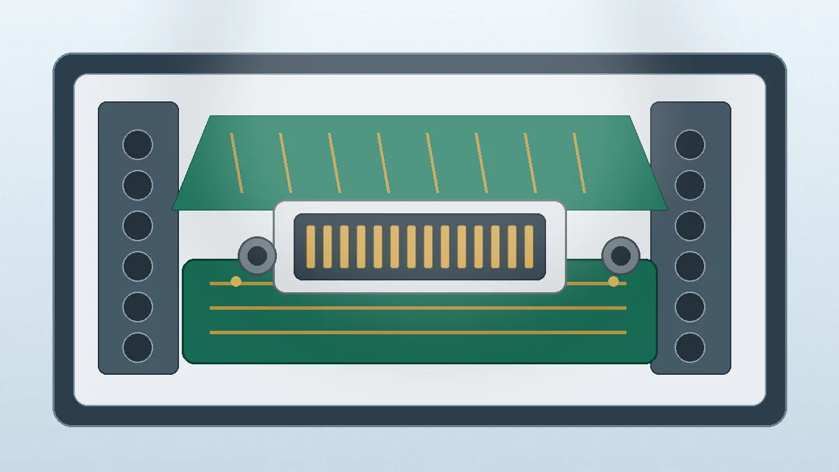
Engineering checkpoint: A connector that fits the footprint can still be unsuitable if the enclosure forces the boards out of alignment, the cable or chassis transfers load into the mating interface, or the selected contact arrangement cannot be validated under the real current and temperature conditions.
Start With the Failure Conditions, Not the Catalog
Harsh environments do not create one single connector problem. Vibration may cause repeated micro-movement at the contact interface. Thermal cycling can change board spacing and load solder joints. Humidity or process residue can increase corrosion and insulation risk. Electrical noise can also turn an otherwise acceptable mechanical connection into a signal-integrity problem.
The first review should therefore describe the stress path. Identify whether the connector is mounted between rigidly fixed boards, between a fixed board and a moving subassembly, or inside a chassis where the PCB guides carry most of the load. That distinction determines whether retention, alignment tolerance, floating movement, or additional mechanical support deserves priority.
For available family-level options, review the Board-to-Board Connectors page. Treat that page as a starting point only. Final selection still depends on drawing review, stack-up, mating height, current assignment, environmental exposure, and validation requirements.
Define the Electrical Boundary Before Choosing Pitch
Pitch is easy to compare, but it is not the first electrical decision. Begin with the pin map and separate power, ground, low-speed signals, and high-speed signals. Then check whether the connector arrangement leaves enough room for routing, return paths, creepage, shielding, and inspection access.
Current and Temperature Rise
Do not multiply a per-contact rating by the number of contacts and assume the total is safe. Adjacent loaded contacts can heat each other, and the usable current may change with ambient temperature, copper area, airflow, and contact grouping. Ask the supplier to review the worst-case simultaneous load and provide the relevant test basis or derating information for the proposed series.
Working Voltage and Spacing
Working voltage must be reviewed together with the PCB layout. The connector housing alone does not guarantee adequate creepage or clearance if pads, vias, or exposed copper reduce the spacing on the board. Confirm the requirement from the system specification, then verify the complete mated interface and land pattern.
Signal Integrity
For fast interfaces, include data rate, reference-plane arrangement, acceptable insertion loss, crosstalk limits, and the complete channel model in the RFQ. A connector may be mechanically compatible while still creating an unacceptable discontinuity. Request SI review only where the project needs it, and confirm what model or test data the supplier can provide.
Build the Mechanical Stack-Up Before Freezing the Footprint
Board spacing should be derived from the enclosure and mounting hardware, not estimated from a nominal connector height. Include PCB thickness, standoffs, guides, fasteners, component keep-outs, tolerance direction, and the sequence used during assembly. A small mismatch can force the connector to absorb load that should have been carried by the chassis.
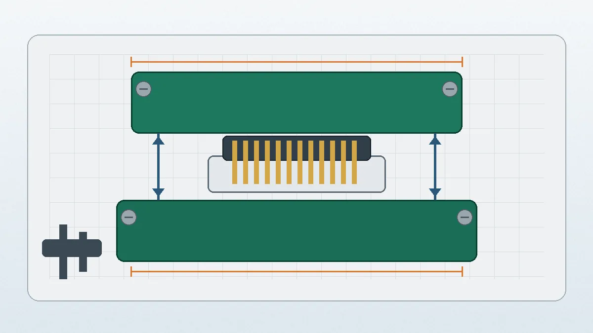
Insertion and extraction force also matter in production. Excessive force can bend boards, damage solder joints, or make the assembly sequence difficult to control. Too little retention may allow movement during transport or operation. If operators can mate the assembly in more than one orientation, add keying or anti-misplug features to the drawing rather than relying on work instructions alone.
| Mechanical Item | What to Confirm | Risk if Missed |
|---|---|---|
| Board-to-board distance | Nominal spacing, tolerance direction, PCB thickness, and standoff control | Preload, incomplete mating, or enclosure interference |
| Alignment method | Board guides, locating pins, housing lead-in, and assembly sequence | Contact stubbing, uneven wear, or damaged solder joints |
| Retention | Required holding force, vibration exposure, and service method | Micro-movement, intermittent contact, or difficult maintenance |
| Inspection access | Visibility, test points, rework access, and mating confirmation | Hidden assembly defects or costly rework |
Choose Fixed or Floating Construction From the Tolerance Budget
Fixed connectors suit assemblies where the boards, guides, and fasteners hold alignment within the connector’s allowable mating window. They are often the simpler choice when the mechanical stack is tightly controlled and the connector is not expected to absorb chassis movement.
Floating Board-to-Board Connectors may be considered when the assembly needs limited tolerance absorption between boards. The floating structure can allow controlled movement within the connector design, but it does not remove the need for board support, vibration testing, or stack-up control. Axial and radial movement, mating force, retention, and allowable PCB offset must be confirmed for the exact series.
The procurement decision should be based on the tolerance budget, not the label “harsh environment.” A floating connector may add value where several tolerances accumulate in the same direction. It may add unnecessary cost or complexity where locating features already control the boards accurately. Ask the mechanical team to show the worst-case offset before requesting a floating option.
Map Environmental Risks to Verification Work
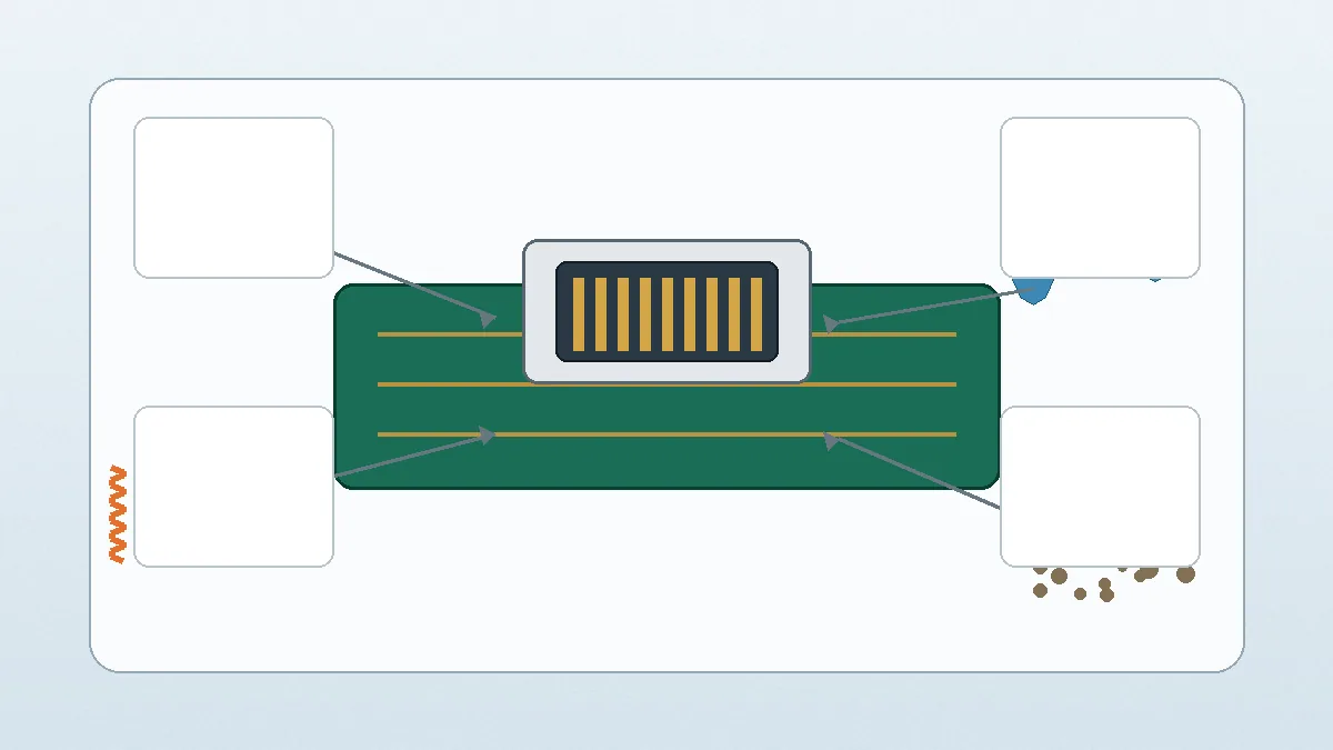
Environmental review should turn each exposure into a test or documentation question. Avoid asking for a generic “industrial grade” declaration. That phrase does not define temperature profile, vibration spectrum, contamination type, mounting condition, or pass/fail criteria.
| Exposure | Engineering Question | Evidence to Request |
|---|---|---|
| Temperature cycling | How much does board spacing change, and where are the local hot spots? | Material data, temperature-rise method, and project-specific test plan |
| Vibration and shock | Which part of the assembly carries the load: connector, board guide, or chassis? | Applicable test condition, fixture description, and discontinuity criteria |
| Humidity and residue | Can moisture or process contamination reach the contact or solder area? | Material and plating details, cleaning controls, and environmental test scope |
| Repeated service | How often will the boards be mated, and who performs the operation? | Mating durability data, handling limits, and inspection instructions |
Prepare an RFQ That Allows a Real Engineering Review
A supplier cannot confirm connector fit from a keyword and pin count. Send enough information to review the full interface. Missing drawings usually lead to broad recommendations that must be repeated later, after the PCB layout is already difficult to change.
Minimum RFQ Package
- Mechanical stack-up drawing: board spacing, PCB thickness, mounting points, enclosure limits, and tolerance direction.
- Pin assignment: power, ground, signal groups, unused contacts, and any sequencing requirement.
- Electrical conditions: working voltage, simultaneous current, signal type, and the worst-case ambient condition.
- Environmental summary: vibration source, thermal cycle, moisture or contamination risk, and service location.
- Assembly requirements: mating direction, insertion access, keying, inspection method, and expected service cycles.
- Project status: prototype timing, sample quantity, drawing release stage, and whether an existing family or custom review is acceptable.
Ask the supplier to return a proposed part drawing, open technical questions, sample plan, and any required validation steps. Do not release the PCB footprint until the mating pair, stack height, orientation, and recommended land pattern are confirmed.
Make the Final Decision With a Controlled Review
Use the industrial board to board connectors selection guide as a decision record rather than a catalog checklist. The final review should show which requirement controls the choice, what remains unverified, and who owns each open item.
Before design freeze, confirm the product drawing, pitch, mating height, pin assignment, alignment tolerance, current loading, environment, test documentation, and supplier review capability. If any of those inputs are still assumptions, keep the connector selection open and schedule a drawing review before ordering production tooling or committing the PCB layout.
Frequently Asked Questions
What should be checked first for an industrial board-to-board connector?
Start with the PCB stack-up, load path, current assignment, signal type, and environmental exposure. Pitch and pin count come after those conditions are defined.
When should a floating board-to-board connector be considered?
Consider it when the worst-case assembly offset or thermal movement exceeds what a fixed interface can accept. Confirm the allowable movement and mating conditions for the exact series.
Is footprint compatibility enough to approve a connector?
No. The mating pair, stack height, orientation, pad layout, keying, insertion force, and enclosure tolerance also require review.
What should be included in the RFQ?
Send the stack-up drawing, pin map, electrical conditions, environmental summary, assembly method, sample timing, and required test documentation.
Send Your Connector Requirement
Share the drawing, PCB stack-up, pin assignment, operating environment, and sample timing. LinkManu can review available connector families and identify the technical items that still need confirmation.

Technical content reviewed by LinkManu Engineering Team
Prepared by LinkManu Editorial Team for B2B connector engineers, sourcing teams, and product development projects. Updated 2026.