
Coaxial Cable Assembly & RFQ Review
How to Put Coaxial Cable Connector Requirements Into an RFQ
For an I/O project, “how to put coaxial cable connector” is not only an assembly question. The purchasing decision depends on whether the cable, connector, panel interface, tooling, inspection method, and acceptance evidence are defined as one controlled package. A sample can look correct and still be unsuitable for repeat production when the drawing leaves strip geometry, shield treatment, center-contact position, or strain relief open to operator judgment.
The practical starting point is the system interface. Confirm the cable specification, mating connector, panel space, routing direction, service environment, and test expectation before requesting a quote. For external and panel-mounted applications, the LinkManu I/O connector overview provides the relevant product-family context, but the exact coax construction still has to be confirmed from the project drawing and equipment requirements.
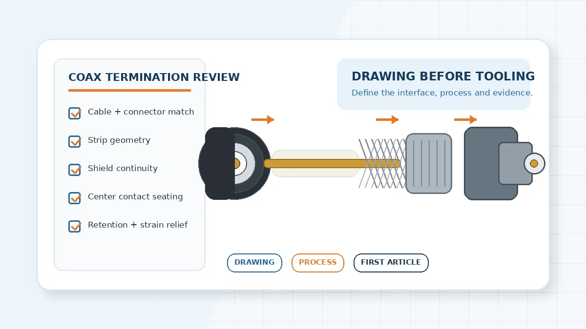
Scope check: this article does not prescribe one universal strip length, crimp height, torque, impedance, or test limit. Those values must come from the selected connector instructions, cable data, customer drawing, and agreed acceptance plan.
How to Put Coaxial Cable Connector Details Into the Drawing
The drawing should remove decisions from the assembly bench. “Fit connector to cable” is not enough. It should identify the exact cable construction and connector series, show the finished orientation, define the panel or bulkhead interface, and state which dimensions are controlled after termination. When the same harness can be installed in more than one orientation, add a clear datum or clocking reference; otherwise a visually acceptable sample may not fit the enclosure.
| Drawing item | What engineering should confirm | Risk if left open |
|---|---|---|
| Cable and connector pairing | Part numbers, cable construction, mating interface, and supplier-approved assembly method. | A connector may physically fit while the ferrule, dielectric support, or contact attachment does not suit the cable. |
| Finished geometry | Overall length, reference points, connector orientation, panel engagement, and keep-out space. | The cable can be terminated correctly but still interfere with the enclosure or adjacent I/O ports. |
| Cable preparation | Which preparation dimensions are controlled and which connector work instruction governs them. | Operators may expose too much dielectric, disturb the braid, or seat the center contact inconsistently. |
| Shield treatment | How the braid is captured, whether stray strands are permitted, and how full shield contact is inspected. | Continuity can pass while shield coverage or mechanical retention remains uncertain. |
| Strain relief and routing | Bend direction, clamp position, boot or sleeve requirements, and allowable load transfer into the connector. | Cable dressing may pull on the termination after the first article has already been accepted. |
A procurement team should also ask who owns each controlled dimension. If a value comes from the connector manufacturer’s work instruction, reference that document and revision. If it comes from the customer assembly drawing, show it directly. Conflicting instructions should be resolved before tooling or sample preparation, not during first-article inspection.
Turn the Assembly Method Into a Controlled Process
Crimp, solder, clamp, and compression-style terminations require different tools and evidence. The RFQ should therefore ask the supplier to state the proposed method rather than allowing “standard process” as the answer. Engineering can then check whether the process is appropriate for the selected cable and connector, production volume, repair policy, and inspection access.
- Confirm preparation tooling. Ask whether the cable is stripped with a dedicated tool, a programmed machine, or a manual fixture. The key judgment is repeatability for the approved cable construction, not the brand of the tool.
- Confirm contact attachment. Request the applicable crimp die, soldering instruction, clamp method, or compression setup. A sample built with prototype tooling should not be accepted as evidence for a different production setup.
- Confirm shield capture. The work instruction should show how the braid is prepared, contained, and inspected before the ferrule or body is closed.
- Confirm connector seating. Define how center-contact depth, dielectric condition, body engagement, and final orientation are verified.
- Confirm change control. Tool replacement, work-instruction revision, cable-source change, or connector revision should trigger an agreed review or revalidation step.
LinkManu source materials list assembly, tooling, stamping, injection molding, and engineering analysis capabilities. Their applicability depends on the connector and RFQ scope. For coax termination, request the proposed process flow and evidence for the actual cable-connector combination rather than assuming every listed capability is used on every project.
Where First-Article Failures Usually Start
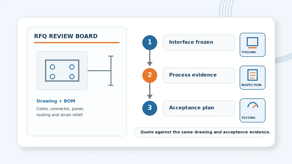
Most preventable disputes begin at the boundary between documents. The cable drawing may define length, the connector instruction may define preparation, and the customer test plan may define electrical acceptance, but no document confirms that the three belong to the same revision-controlled assembly. During review, look for these gaps:
- Prototype-to-production mismatch: the first sample is built by an engineer, while production uses a different tool, fixture, or operator instruction.
- Uncontrolled shield strands: visual criteria do not state how braid disturbance or stray strands are judged before the connector body is closed.
- Contact position ambiguity: the drawing lacks a measurable reference for a center contact that is too proud, too recessed, or not fully seated.
- Retention tested at the wrong point: a pull check is performed on the cable assembly without showing whether the load is carried by the intended retention feature.
- Routing added after approval: the final enclosure bend, clamp, or tie point applies load that was absent from the bench sample.
- Acceptance data without traceability: results are supplied, but the report cannot be tied to the material lot, drawing revision, tool setup, or inspected sample.
Do not solve these gaps by adding arbitrary numeric limits. Instead, identify the governing source for each limit and ask the supplier to show how it will be measured. That keeps the RFQ technically specific without turning an unverified web value into a project requirement.
Define Acceptance Evidence Before Quotation
The test plan should match the failure risk and the customer’s system requirement. A continuity check alone cannot demonstrate shield construction, contact seating, cable retention, or RF performance. At the same time, requesting every possible test can add cost without improving the decision. Use the table below to assign evidence deliberately.
| Evidence | Decision to make before RFQ | What to request |
|---|---|---|
| Visual and dimensional inspection | Which finished dimensions and visible conditions determine acceptance? | First-article report, measurement method, drawing references, and photographs where useful. |
| Termination cross-section | Is destructive inspection needed to verify ferrule fill, conductor condition, or internal seating? | Cross-section criteria, sample timing, and revalidation trigger. |
| Electrical checks | Which short/open, insulation, withstand, or signal checks are required by the project specification? | Test method, equipment, sampling level, limits, and report format. |
| Mechanical retention | Which interface is being evaluated and how will the assembly be fixtured? | Load direction, fixture concept, acceptance source, and whether testing is destructive. |
| Process records | Which preparation, crimp, soldering, or torque settings need lot traceability? | Recorded parameters, calibration status, operator or station identification, and change-control method. |
Some verification may be performed by an external laboratory depending on the project. State this during quotation and confirm who owns sample preparation, test fixtures, report review, and failure follow-up. “Testing can be arranged” should not be interpreted as a fixed in-house capability or a standard test package for every order.
Build an RFQ Package Suppliers Can Review
A usable RFQ lets two suppliers quote the same technical scope. Before release, assemble the following items and remove contradictions between them:
- Assembly drawing: finished length, connector orientation, panel interface, routing notes, controlled preparation features, and revision history.
- BOM: cable, connector, contacts, ferrule, boot, heat-shrink, clamp, labels, and any customer-supplied components.
- Application conditions: installation location, service access, vibration or movement concerns, environmental exposure, and maintenance expectations that affect selection.
- Volume and build stages: prototype quantity, pilot expectations, forecast range, and whether production tooling must be used for samples.
- Acceptance plan: inspections, tests, sampling, document format, nonconformance handling, and revalidation triggers.
- Supplier deliverables: drawings, process flow, first-article report, material documentation, test data, and traceability records required with the shipment.
Quotation check: compare exclusions as carefully as unit price. A lower quote may omit production tooling, destructive inspection, test fixtures, documentation, or revalidation after a material change.
What to Confirm Before Releasing Samples
Freeze the cable and connector part numbers, drawing revision, mating interface, panel space, routing direction, acceptance criteria, and required evidence. Then ask the supplier to identify open questions before building samples. If any of those inputs are still provisional, label them clearly and agree on the review point that will freeze them.
For a project-specific review, send the drawing, BOM, target application, expected quantities, and acceptance requirements through LinkManu engineering support. The next decision should be whether the proposed connector and termination process can be evaluated against your actual interface—not whether a generic coax connector can be attached on a bench.
Frequently Asked Questions
How do you put a connector on coaxial cable for production?
Use the connector’s approved preparation and termination method for the exact cable. Control the tools, document the setup, inspect contact and shield condition, and link the first-article results to the drawing revision.
How do I choose the correct coax connector?
Match the mating interface, cable construction, panel space, operating environment, signal requirement, assembly method, and service needs. Confirm all project-specific limits from the customer drawing and selected component documentation.
What should a first-article report include?
Include controlled dimensions, visual criteria, applicable electrical or mechanical results, drawing and BOM revisions, sample identification, tooling or process references, and any deviations.
Should the RFQ specify crimp or solder termination?
Specify a method when the design already requires it. Otherwise ask suppliers to propose a method for the selected cable and connector, then compare process control, inspection access, repair policy, and evidence.
Send Your Connector Requirement
Share the drawing, BOM, target application, quantity range, and required inspection or test documentation for an RFQ-readiness review.

Technical content reviewed by LinkManu Engineering Team
Prepared by LinkManu Editorial Team for B2B connector engineers, sourcing teams, and product development projects. Updated 2026.