
I/O Connector Engineering Guide
Connector Type SMA: Engineering RFQ Checklist
A connector type SMA may look like a small catalog item, but the approval decision belongs to the complete I/O assembly. Panel geometry, PCB location, cable routing, mating access, environmental exposure, and the evidence supplied with production samples all affect whether the interface is suitable. The useful question is not simply “Which SMA fits?” It is “What must be confirmed before this part is released into the design and supply chain?”
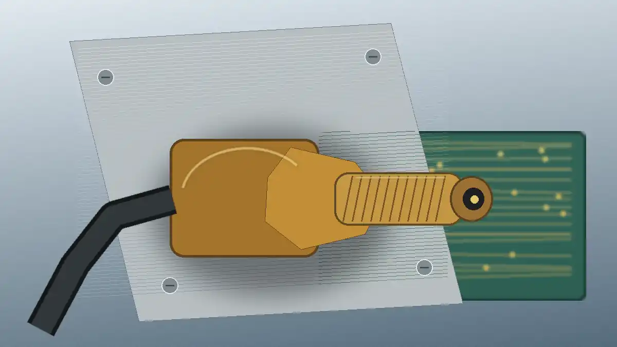
Start with the I/O interface, not the catalog page
Two parts described with the same connector family name can still create different installation risks. A bulkhead arrangement depends on panel thickness, cutout shape, nut access, gasket placement, and cable clearance. A board-mounted arrangement adds footprint accuracy, board-edge position, solder-joint loading, and enclosure alignment. Procurement should therefore request a drawing that matches the proposed mounting style instead of approving a part from a product photo or a short description.
The first engineering gate is mechanical compatibility. Confirm which side of the panel is accessible during assembly, whether the mating cable can be tightened without contacting nearby hardware, and where cable strain will be transferred. A connector that fits the nominal opening may still be unsuitable if the cable bend, tool access, or repeated service load reaches the PCB or solder joints.
Engineering decision: do not approve the connector until the enclosure drawing, panel cutout, PCB position, mating direction, and cable exit have been reviewed together.
For the broader role of external interfaces in an equipment design, see I/O Connectors for External and Panel Interface Projects. That context helps separate a connector-family decision from the mechanical and documentation work needed for a specific assembly.
Freeze mechanical fit before sample approval
Sample evaluation should use the same dimensional references that will control production. Request an identified drawing revision and check the body envelope, mounting features, contact position, panel interface, board footprint where applicable, and the clearance required by the mating part. If the supplier changes the drawing after the sample is accepted, the change should trigger another review rather than being treated as an administrative update.
| Mechanical review item | Project question | Evidence to retain |
|---|---|---|
| Mounting style | Is the connector panel-mounted, board-mounted, cable-ended, or part of a combined assembly? | Approved assembly drawing and mounting view |
| Panel and enclosure fit | Are cutout, thickness, hardware access, and mating clearance defined? | Panel drawing with tolerances and assembly notes |
| PCB relationship | Can panel and board tolerances load the contact or solder joints? | PCB layout, stack-up view, and first-article measurements |
| Cable routing | Where are bend, pull, and service loads transferred? | Cable drawing, routing model, or assembly photograph |
Dimensional articles can help during early comparison, but they do not replace the project drawing. Use the SMA connector dimensions guide to identify which dimensions require attention, then confirm the actual values and tolerances on the selected supplier document.
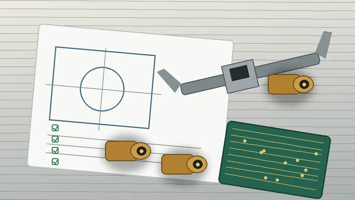
Write electrical needs as acceptance criteria
Catalog headings such as impedance, frequency range, insertion loss, return loss, insulation resistance, and contact resistance are not enough by themselves. The RFQ should state which characteristics matter to the design, the operating band or test condition defined by the project, the applicable test method, and the evidence required for approval. Exact limits should come from the customer drawing, validation plan, or qualified technical source—not from an unrelated supplier page.
| Parameter area | What the buyer should define | What to request from the supplier |
|---|---|---|
| Signal performance | Required operating band and allowable system loss or reflection | Test plots, method, fixture information, and sample identification |
| Interface continuity | Which inner and outer contact checks are part of acceptance | Measurement results and the referenced test procedure |
| Electrical safety checks | Whether insulation or dielectric tests apply to the project | Test condition, acceptance criterion, and report traceability |
| Post-stress performance | Which values must be rechecked after mating or environmental exposure | Before-and-after data from identified samples |
Termination work also belongs in the electrical review. Cable preparation, conductor seating, soldering or crimping method, and strain relief can change the finished assembly even when the connector body is unchanged. The coax connector installation guide provides assembly context; production instructions should still be based on the approved connector and cable combination.
Environmental and service conditions change the RFQ
An indoor bench connection and an exposed panel interface should not share the same unchecked assumptions. The buyer should state where the connector is installed, whether condensation or contaminants are possible, how often it is mated, and whether the cable is handled during maintenance. Environmental ratings or durability claims should be accepted only when the scope, test condition, and exact part or assembly are clear.
- Temperature: define operating and storage conditions from the product validation plan, then request evidence for the proposed construction.
- Humidity or condensation: confirm whether sealing is required at the connector, the panel interface, or both.
- Vibration and shock: review retention, cable support, panel hardware, and PCB loading instead of checking only the connector body.
- Corrosive exposure: identify the environment and ask which material, finish, and test documentation apply to the quoted part.
- Service frequency: define expected mating and maintenance activity, then request durability evidence and post-test electrical results.
A practical risk check is to ask what happens after the environmental test. A pass statement without post-test dimensional or electrical results may not answer whether the interface still meets the application requirement.
Build documentation into supplier approval
The RFQ should define the records needed at quotation, sample approval, and production release. This prevents a common sourcing problem: engineering approves a sample, but purchasing later receives a production part without the drawing revision, material information, or test evidence used during the original decision.
- Drawing control: identify the supplier drawing, revision, critical dimensions, and customer-controlled requirements.
- Sample traceability: record the part designation, lot or sample reference, test date, and report linked to the evaluated pieces.
- Material and process declarations: request only the information needed by the application, compliance plan, and change-control process.
- Inspection plan: agree which dimensions and electrical checks apply to first articles and ongoing lots.
- Change notification: define which material, tooling, process, site, and drawing changes require customer review.
- Continuity planning: confirm lead-time assumptions, tooling ownership where relevant, and the evidence needed before approving an alternate source.
LinkManu’s approved company materials list tooling, stamping, injection molding, assembly, and inspection as available process capabilities. Their relevance depends on the quoted connector and RFQ scope, so buyers should ask which steps apply to the proposed project and which tests are performed internally or arranged externally. The same materials reference IATF 16949 and ISO 14001; certification scope and manufacturing-site coverage should be checked during supplier qualification.
A practical connector type SMA RFQ sequence
A short sequence keeps the engineering and purchasing reviews aligned:
- Send the current panel, PCB, cable, or assembly drawing rather than a screenshot or catalog link alone.
- State the mating interface, mounting arrangement, cable direction, service access, and target environment.
- List electrical characteristics that require evidence, but use project-controlled acceptance limits.
- Ask the supplier to identify the drawing revision and production-equivalent sample being quoted.
- Define first-article measurements, test records, and any post-environment verification before ordering production quantity.
- Close open questions in writing and update the controlled drawing or specification before final approval.
Next step: confirm the drawing, mounting geometry, mating interface, PCB or cable relationship, electrical acceptance plan, environment, test documentation, and supplier process scope before releasing the connector.
Frequently Asked Questions
How should engineers choose a connector type SMA?
Start with the complete I/O assembly. Confirm mounting, mating access, cable or PCB loading, electrical acceptance criteria, environment, and the documents tied to the production sample.
Can an SMA connector be approved from a datasheet alone?
Usually not for a controlled production design. The datasheet should be checked against the actual drawing, installation stack-up, sample measurements, and required test evidence.
What does “pinout” mean for an SMA interface?
Review the center signal path and the outer conductive return path, then confirm how both connect through the cable, PCB, panel, and enclosure.
What should be included in an SMA connector RFQ?
Include the controlled drawing, mounting and mating details, cable or PCB information, project-specific electrical criteria, environment, sample quantity, inspection plan, and required reports.
Send Your Connector Requirement
Share the drawing, BOM, panel or PCB context, target environment, and documentation requirements. The review should resolve open mechanical, electrical, and supplier-qualification questions before final selection.

Technical content reviewed by LinkManu Engineering Team
Prepared by LinkManu Editorial Team for B2B connector engineers, sourcing teams, and product development projects. Updated 2026.