
Connector Engineering Guide
Types of FPC Connector Locks: Selection Checks for Wire-to-Board Assemblies
Choosing among the types of FPC connector locks is not a cosmetic detail. The actuator changes how the cable is inserted, what access the operator needs, how partial seating is detected, and whether the connection can be serviced without damaging the FPC. Before the PCB and cable drawings are released, the lock should be reviewed together with the contact orientation, cable end, component clearance, expected handling, and inspection method.
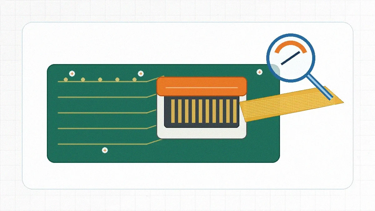
Engineering judgment: A lock style is suitable only when the drawing, FPC end, assembly motion, access envelope, and required documentation agree. A familiar actuator name alone is not enough for part approval.
Treat the Lock as an Assembly Interface, Not a Catalog Label
An FPC connector can look correct in a product table and still be awkward on the actual board. A slide actuator needs room for lateral movement. A flip actuator needs a clear sweep above or beside the connector. A back-flip design changes where the operator places a finger or tool. When another component, enclosure wall, heat spreader, or harness blocks that motion, the chosen lock may be difficult to close even though the connector footprint fits.
The practical review starts with the assembly sequence. Determine who inserts the cable, from which direction, with what visibility, and whether the cable will be removed during test or service. Then confirm how the operator recognizes full insertion before closing the lock. If the inspection plan cannot distinguish a fully seated FPC from a skewed or shallow insertion, the risk is a process problem rather than a simple connector problem.
For projects that combine flexible circuits with other PCB-to-wire interfaces, the related wire-to-board connector family should be reviewed separately. The FPC lock does not replace checks for terminal, housing, wire, current, or environmental requirements elsewhere in the assembly.
Compare Lock Families by Motion, Access, and Cable Handling
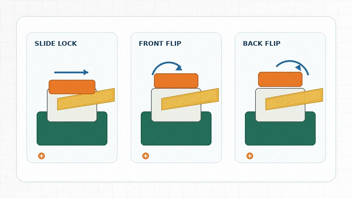
Compare the common types of FPC connector locks by actuator motion and production handling. Final suitability still depends on the supplier drawing and sample.
| Lock family | Operator motion | Engineering check | Typical risk to review |
|---|---|---|---|
| Slide lock | The actuator moves laterally. | Confirm side clearance, access to both ends, and a visible fully closed position. | A nearby component or enclosure can prevent complete travel. |
| Front-flip lock | The actuator opens at the cable-entry side. | Check the insertion view and the actuator sweep at the mating face. | The cable or adjacent hardware may obstruct the closing motion. |
| Top or rear flip lock | The actuator rotates upward or backward. | Verify vertical access and confirm that the operator will not load the hinge sideways. | Limited overhead space can force an angled closing action. |
| Back-flip lock | The actuator opens away from the cable entry. | Review cable bend direction, finger access, and the area behind the connector. | The preferred cable route may conflict with the actuator position. |
| LIF or non-ZIF | The cable is inserted against contact force, with no conventional flip actuator. | Confirm the approved insertion method and whether reconnection is expected. | Uncontrolled insertion can damage the cable end or contacts. |
| One-action or stuffer-style | The cable end or a separate insertion feature completes the locking action. | Confirm cable-end preparation, stiffener details, and the exact assembly sequence. | A part-number change may also require an FPC-tail or tooling change. |
Selection Checks to Complete Before Drawing Release
Do not approve the lock from a connector rendering alone. Use the connector drawing, the FPC drawing, and the board layout in the same review. The following checks turn a generic lock preference into a controlled design decision.
| Review item | What to confirm | Release condition |
|---|---|---|
| FPC end geometry | Contact side, exposed conductor length, stiffener, tabs or notches, and insertion datum. | The supplier drawing and cable drawing describe the same mating interface. |
| PCB access envelope | Actuator travel, finger or tool path, surrounding components, and enclosure clearance. | The lock can be opened and closed without forcing the cable or nearby parts. |
| Handling profile | Factory-only mating, rework, functional test, field service, and the responsible operator. | The selected family matches the expected disconnect and reconnection process. |
| Electrical fit | Required current, voltage, contact arrangement, and any signal-related constraints. | The connector specification is confirmed independently of the lock name. |
| Environment and validation | Vibration, temperature exposure, chemicals, cable pull, and required qualification evidence. | Test items and acceptance criteria are documented rather than assumed. |
| Inspection method | Visual indicators, seating reference, actuator position, and defect escalation. | Production can identify incomplete insertion before electrical test or final assembly. |
Risk boundary: The lock mechanism does not establish the connector’s current, voltage, material, plating, temperature, or cycle capability. Those items must come from the approved part drawing, specification, and project test plan.
Use Samples to Expose Assembly Problems Before Tooling
A sample review should reproduce the intended production motion, not just prove that the cable can be connected once. Use the proposed FPC end and board orientation. Insert the cable while observing whether the contacts and alignment features remain visible. Close the actuator using the planned finger or tool access, then inspect the cable datum and lock position from the same angle available on the line.
Repeat the handling check with representative cable-end tolerances and with the planned cable route applied. Watch for skewed entry, hinge loading, actuator flex, cable buckling, or a lock that appears closed before the FPC reaches its datum. Record the sequence with photos or a work instruction. When different operators obtain different results, change the process or connector choice before approving the drawing.
Documentation requests should match the project risk. State the required dimensional, actuator-force, mating, environmental, and material evidence in the RFQ. Do not assume every supplier uses the same test method or that a catalog family covers the selected part.
Procurement Risks That Often Appear After Part Selection
A lock change can affect more than the connector line item. The mating FPC end, stiffener, assembly fixture, inspection instruction, and approved part number may all need review. Procurement should therefore ask whether alternate lock styles share the same footprint and cable interface or require a controlled redesign. “Similar appearance” is not evidence of interchangeability.
Supplier review should also separate standard availability from project-specific support. Confirm sample status, drawing revision, tooling responsibility, documentation scope, change-control expectations, and the test evidence required before production approval. For related housing and interface questions, the current file set also permits reference to wire-to-board connector housing selection and LinkManu engineering contact.
Manufacturing Review for Consistent Lock Operation
Lock consistency depends on the interaction between the molded actuator, housing features, stamped terminals, and assembly process. The manufacturing capability information supplied for this article lists tooling, injection molding, stamping, assembly, and inspection steps. Which steps apply should be confirmed for the proposed connector rather than presented as a universal process.
For a project-dependent review, engineering analysis may include Pro-E modeling, Moldflow analysis, or ABAQUS terminal stress analysis. These tools do not replace sample evaluation, but they may help investigate actuator fill, deformation, terminal interaction, or tolerance concerns when the RFQ scope justifies the work. Specialized validation may also be arranged outside the factory when the required equipment is not part of the normal process.
Quality planning should define what is checked during molding, terminal production, assembly, and outgoing inspection. Useful questions include how actuator presence and position are verified, how cavity or batch issues are traced, and what evidence is retained when a lock complaint is investigated. The goal is a reviewable control plan, not a broad statement that every lock will perform identically in every application.
What to Send for an Efficient Supplier Review
Prepare the connector drawing or target footprint, FPC drawing, contact orientation, pitch and position count, board layout around the actuator, cable route, handling profile, application environment, and required test documentation. Also identify whether the connection is factory-only, used during test, or accessible in the field.
The next decision is concrete: select the likely lock family, mark the actuator clearance on the PCB or enclosure drawing, confirm the FPC end and contact side, and request the exact supplier drawing plus sample and test-document plan. Do not freeze the part number until those items agree.
FAQ: FPC Connector Lock Types
What are the main types of FPC connector locks?
Common mechanisms include slide, front-flip, top or rear flip, back-flip, LIF, non-ZIF, and one-action or stuffer-style designs. Confirm the exact actuator motion and cable interface on the supplier drawing.
What is the difference between ZIF, LIF, and non-ZIF?
ZIF uses an actuator to release contact force for insertion. LIF reduces insertion force without the same locking action. Non-ZIF relies on direct insertion against the contacts. The handling profile determines which family is appropriate.
What are the three basic FPC connector families?
For lock selection, the useful high-level grouping is ZIF, LIF, and non-ZIF. Each group can be divided further by actuator style, mounting, contact orientation, and cable-end requirements.
Send Your Connector Requirement
Share the drawing, FPC details, board layout, target application, handling profile, and documentation requirements. LinkManu can review fit, sample needs, and RFQ readiness before final part selection.

Technical content reviewed by LinkManu Engineering Team
Prepared by LinkManu Editorial Team for B2B connector engineers, sourcing teams, and product development projects. Updated 2026.