
Board-to-board connector selection
Circuit Board Connector Types for PCB Stack and BOM Review
Searches for circuit board connector types often start as a parts-list question. For a real board stack, the better question is narrower: which connector type can mate within the enclosure, tolerate the assembly process, carry the required signals or power, and be supported with drawings, samples, and test evidence before the BOM is frozen?
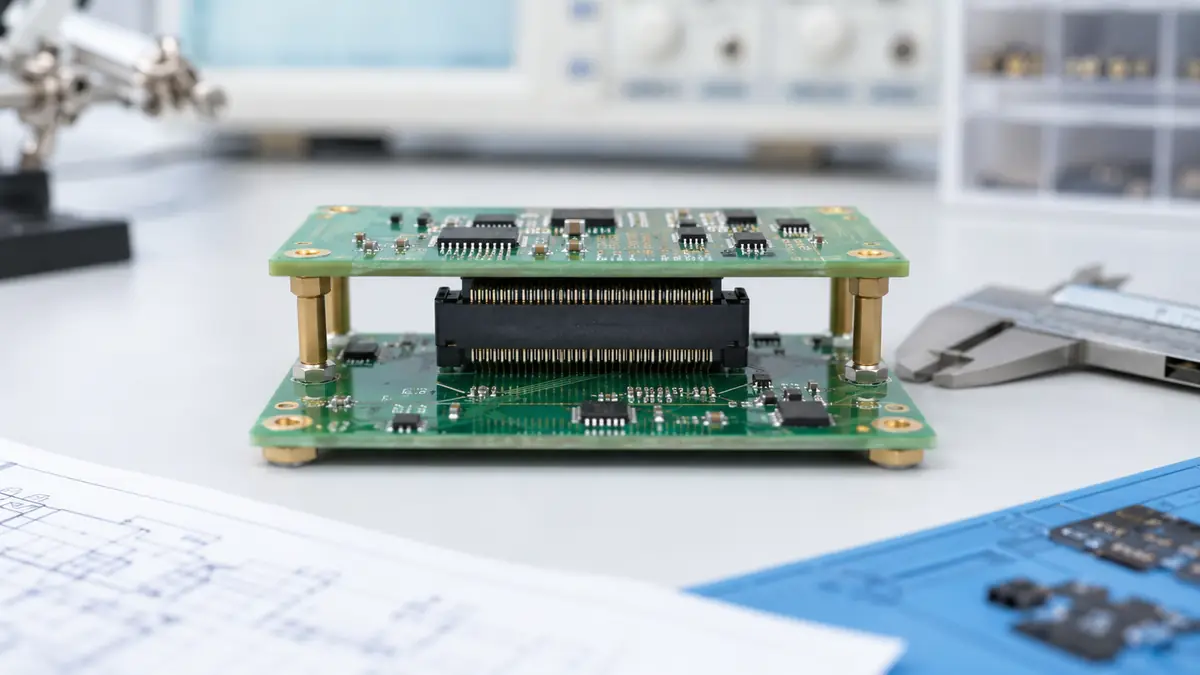
Treat circuit board connector types as a project filter
A board-level connector can describe several very different interfaces. Board-to-board connectors join two PCBs directly. Wire-to-board connectors bring discrete wires or cable assemblies onto a PCB. I/O connectors connect the product to an external interface. Card edge and power connector families may also appear in the same design review. If the assembly has two PCBs that must mate inside one enclosure, the buyer should first narrow the discussion to board-to-board options and then confirm whether the design needs a fixed, floating, stacking, or right-angle architecture.
The practical risk is that teams choose a connector by pitch or contact count before checking whether the mated pair fits the mechanical envelope. A connector that looks acceptable on the footprint can still fail the project if its assembled height conflicts with the enclosure, if the pick-and-place process cannot hold the required alignment, or if the selected termination does not suit the production process. For early RFQ review, the drawing should show board spacing, mating direction, keep-out area, and any enclosure features that can push the two PCBs out of position.
Engineering check: do not approve a board-to-board connector from a top-view footprint only. Request the 2D drawing, 3D model, mating-height information, and sample plan before locking the PCB layout.
Compare connector families by failure risk, not only by name
The name of the connector family is only a starting label. The more useful comparison is the risk each family carries in the actual product. A fixed stacking connector can be suitable when board alignment is controlled by the mechanical structure and the enclosure does not introduce meaningful side load. A floating board-to-board connector deserves review when tolerance stack-up, vibration, or repeated thermal movement may stress solder joints or contact points. A right-angle connector can solve board orientation problems, but it also changes the keep-out area and the direction of insertion force.
| Connector family | Useful when | Risk to check before BOM approval | Documents to request |
|---|---|---|---|
| Fixed board-to-board stacking connector | Parallel PCBs need a compact direct connection and the mechanical design controls alignment. | Side load from board offset can transfer stress into solder joints if the enclosure tolerances are loose. | Footprint, mating-height drawing, 3D model, and sample fit report. |
| Floating board-to-board connector | The design needs tolerance absorption or board-mating flexibility. | Floating movement is not a universal fix; the allowable movement and load direction must match the drawing. | Floating range from the product drawing, application notes if available, and sample validation plan. |
| Right-angle board connector | Two boards or modules need to meet at an angle rather than in a vertical stack. | Insertion direction, connector height, and neighboring components can block assembly access. | Mechanical drawing, orientation marking, and enclosure clearance check. |
| Pin header and socket | The project has moderate density needs, simple assembly requirements, and controlled mating conditions. | Low-cost parts can still create rework if keying, retention, or plating requirements are not confirmed. | Contact material, plating, retention detail, and sample inspection criteria. |
For LinkManu project discussions, board-to-board connector projects can be reviewed across listed pitch families, with final feasibility confirmed by the customer drawing, sample, mating height, and application requirements. The product overview for Board-to-Board Connectors for Compact PCB Interconnects is the relevant internal reference when the project involves two PCBs rather than a wire harness or external cable interface.
Board stacking and mating height decide the layout earlier than many teams expect
Pitch and contact count receive most of the early attention, but stacking height often decides whether the layout is feasible. The mated connector height affects standoffs, heat sinks, shields, displays, daughtercards, and the final enclosure. A small change in mating height can force a component relocation or a board support change. That is why the connector drawing should be checked together with the enclosure model before the footprint is released to PCB layout.
Mating direction matters for assembly as much as it matters for electrical connection. A vertical stack may be simple to inspect, but the assembly line still needs a controlled way to press the boards together without bending the PCB. A right-angle interface may fit the enclosure better, but the operator or fixture needs access for insertion. If the product will be serviced, the review should also ask whether the connector is expected to be mated only once during production or disconnected during maintenance. Those two cases can lead to different retention and durability requirements.
Alignment tolerance is the other early lock. When bosses, screws, displays, or plastic housings locate the boards, the connector is rarely the only part controlling position. The tolerance loop should include the PCB fabrication tolerance, component placement tolerance, enclosure features, screw locations, and any compression or movement after final assembly. If the total variation is larger than the connector can safely accept, the issue should be found in CAD review or sample build, not after a pilot run.
Use floating connectors only when the tolerance problem is real and defined
Floating board-to-board connectors can be useful when the project has unavoidable board-mating variation. They should not be treated as a general insurance policy. The drawing still needs to confirm allowable displacement, mating direction, contact engagement, and mounting method. If the product has vibration or thermal movement, the review should ask whether the movement is lateral, angular, vertical, or a combination. A floating structure that helps one direction may not protect the assembly from another load path.
Procurement teams should also check whether the need for floating movement is created by the connector or by the surrounding design. If a plastic housing locates the two boards poorly, a floating connector may reduce stress but may not fix the root cause. If the board supports can be improved, a simpler connector may still be acceptable. The decision should be made after reviewing the tolerance loop, not after comparing product names. For projects where tolerance absorption is part of the requirement, the Floating Board-to-Board Connectors page gives the correct product-family context.
Procurement judgment: ask the supplier to confirm whether floating movement is required, optional, or unnecessary for the actual assembly. This prevents paying for a feature that does not solve the project’s main risk.
Electrical ratings need project derating, not catalog reading
Current rating, voltage rating, contact resistance, and signal behavior should be handled as project checks. A rating on a catalog page may be measured under conditions that do not match the customer enclosure, active contact count, board copper, airflow, or operating temperature. For a mixed signal-and-power connector, the review should ask which contacts are energized at the same time and whether adjacent contacts affect temperature rise. If the application uses impedance-controlled lines, the connector should be included in the signal-path review rather than treated as a mechanical accessory.
For high-density board stacks, electrical and mechanical decisions are linked. A smaller pitch may save board area, but it can tighten routing, inspection, cleaning, and assembly constraints. A larger connector may be easier to handle, but it may force the board outline or shielding to change. A buyer comparing circuit board connector types should therefore ask for the electrical load, the number of active contacts, the environment, and the available board area in one review package. Splitting those items across separate emails increases the chance that a supplier quotes a part that fits only part of the requirement.
Environmental exposure changes the supplier questions
Board-to-board connectors inside an enclosure are still exposed to real operating conditions. Heat from nearby components, humidity, flux residue, dust, vibration, and handling during assembly can affect the interconnect. The article should not assume that a connector family is automatically suitable for automotive, industrial, consumer, or outdoor use. The safer approach is to describe the environment and ask which tests or material checks are relevant for that specific project.
Company materials describe connector quality and testing capabilities, with some testing outsourced when required. That means the right wording in an RFQ is not “send all test reports.” The better request is: specify the operating environment, then ask which inspection or test documentation can be provided or arranged for the selected connector. Depending on the project, the review may include fit checks, insertion and extraction force, temperature rise, hi-pot, impedance, salt spray, or environmental testing. Each item should be tied to the drawing or end application instead of added as a generic checklist.
Prepare the supplier review package before asking for samples
A sample request is most useful when the supplier receives enough context to screen the design first. Send the PCB footprint or proposed drawing, board stack height, mating orientation, current and signal requirements, expected environment, target production volume, and any inspection requirements. If the part must mate with an existing board, include the mating connector details and a clear statement that compatibility must be checked against drawings, not assumed from visual similarity.
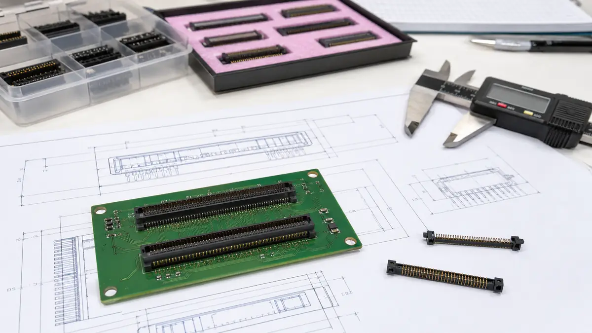
Engineering support such as Pro-E modeling, Moldflow analysis, ABAQUS terminal stress analysis, and SI simulation may be arranged on a project-dependent basis. This should be written as a review option, not as a promise that every project receives every analysis step. For a simple board stack, a drawing and sample fit check may be enough. For a compact assembly with tight tolerance or controlled impedance, the review package should be more detailed before the first production quotation.
When a lower unit price creates a higher project cost
Connector cost is visible in the BOM. Rework cost is usually hidden until the first build. A part that saves a small amount per unit can become expensive if it causes hand fitting, inconsistent mating feel, inspection failures, or a second PCB revision. Procurement should therefore compare price together with sample lead time, drawing support, documentation quality, and the supplier’s ability to discuss the application. A quote that lacks the drawing basis for pitch, mating height, and contact arrangement should not be treated as equivalent to a reviewed connector proposal.
For a project team, the most useful decision record is simple: why this connector family was chosen, what risk it controls, what assumptions remain open, and which documents support the choice. That record helps engineering, quality, and purchasing review the same facts when the design moves from prototype to pilot production. It also reduces the chance that a later cost-down substitution changes the mechanical or electrical behavior without anyone noticing.
Next steps before you freeze the board-to-board BOM
Before approving circuit board connector types for a stacked PCB design, confirm the drawing, pitch, mating height, contact count, current rating, signal requirements, environment, sample plan, and supplier documentation. When any of those inputs is missing, mark it as an open engineering item instead of filling the gap with a catalog assumption. The next practical step is to prepare a compact review package: PCB layout or footprint, 3D envelope, operating conditions, expected production volume, and the test or inspection documents required by your customer.
FAQ: circuit board connector types for PCB projects
What are the main circuit board connector types?
Common board-level families include board-to-board, wire-to-board, I/O, card edge, power, and pin header/socket connectors. For stacked PCBs, start with board-to-board options.
When should I consider a floating board-to-board connector?
Consider it when the tolerance loop shows real board-mating variation or movement. Confirm the allowable movement and load direction from the connector drawing.
Can I choose a connector from pitch and contact count alone?
No. Pitch and contact count do not confirm mating height, enclosure clearance, alignment tolerance, current derating, or sample fit.
What should I send for a supplier feasibility review?
Send the drawing or footprint, board spacing, mating direction, electrical load, environment, target volume, and required test or inspection documents.
Send Your Connector Requirement
Share the drawing, mating height, pitch, contact count, current or signal requirement, application environment, and documentation needs so the connector review can start from confirmed project inputs.

Technical content reviewed by LinkManu Engineering Team
Prepared by LinkManu Editorial Team for B2B connector engineers, sourcing teams, and product development projects. Updated 2026.