
Connector Engineering Guide
Power and Signal Connector Selection Guide for PCB Design
A mixed power and signal connector is not just a part that fits the PCB footprint. It becomes part of the current path, the signal return path, the mechanical stack-up, and the production test plan. A useful power and signal connector selection guide starts with the conditions that can break the design: current loading across adjacent pins, heat near signal contacts, board space, operator mating, and the environment around the finished product.
For an engineering buyer, the first purchasing question is not “which series is cheapest?” It is whether the supplier can confirm the drawing, sample, material choice, termination process, and inspection evidence needed before the board is released. If any of those inputs are missing, the connector may pass a quick bench check and still create debug work later.
Define the Board Conditions Before Shortlisting Parts
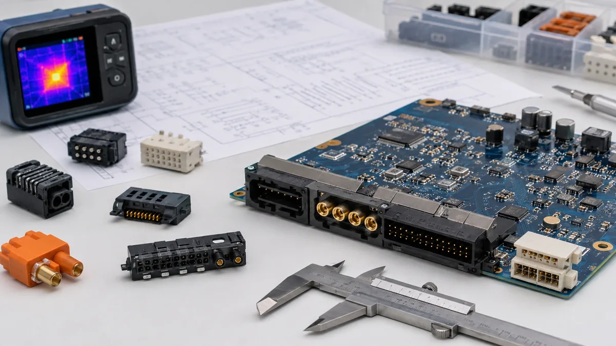
A connector search should begin with the board interface. List the rails, signal types, pin count, mating direction, available height, keep-out zones, and whether the connector will be handled by operators or only during assembly. This step prevents a common sourcing mistake: choosing a part that matches pitch and position count but does not match the actual load, routing, or service condition.
Current rating needs special care. Do not treat a single datasheet value as proof for the final assembly. Ask whether the rating was tested with all relevant contacts loaded, what derating curve applies at the expected ambient temperature, and whether the sample layout matches your pin assignment. If a power contact is placed next to sensitive signal pins, heat and return-current behavior should be reviewed together.
Engineering check: keep exact current, voltage, temperature, flame rating, and safety requirements as project inputs until the drawing, datasheet, sample, or test report confirms them.
Separate Power Risk From Signal Risk, Then Review the Boundary
Power contacts mainly fail through heating, resistance growth, poor termination, or insufficient mechanical retention. Signal contacts are more sensitive to pin assignment, return path, contact stability, and noise near switching or high-current areas. The risky area is the boundary between the two. A compact hybrid connector can save board space, but only if the layout keeps power heat, signal routing, and mating tolerance under control.
This is where a power and signal connector selection guide should be practical. For a motor drive, control module, battery interface, or industrial I/O board, ask which pins carry sustained load, which pins carry feedback or communication, and whether the mating interface sees vibration, humidity, repeated service, or cleaning chemicals. A connector that is acceptable inside a sealed product may be a poor choice on a board edge that is opened during maintenance.
Compare Architecture and Termination Together
Architecture and termination style should be selected as one decision. A high-current contact with the wrong PCB termination can still create solder voids, hole tolerance problems, or assembly variation. A fine-pitch signal section may look efficient until inspection shows coplanarity or rework risk.
| Selection area | What to check | Risk if ignored |
|---|---|---|
| Power contact layout | Pin assignment, loaded contacts, heat path, and derating evidence. | Voltage drop, contact heating, or late PCB layout change. |
| Signal section | Routing distance from power pins, return path, shielding need, and board keep-out. | Noise, unstable readings, or failed functional tests. |
| Termination style | Through-hole, surface-mount, press-fit, or crimp process fit with your assembly flow. | Solder quality issues, fixture changes, or weak retention. |
| Mechanical fit | Mating direction, latch access, board-to-panel clearance, and operator use. | Mis-mating, service damage, or enclosure interference. |
| Supplier evidence | Drawing, material record, sample plan, inspection method, and test documentation. | Unverified claims become production risk. |
For PCB projects that start from a power interface, LinkManu’s power connector portfolio can be used as a reference point for discussing package style, contact form, and project fit. The final choice still needs project drawings and sample confirmation.
Material and Environment Questions That Change the Decision
Material choices should be treated as engineering evidence, not decoration on a datasheet. Terminal material affects spring behavior and retention. Plating selection affects low-level signal stability, corrosion resistance, and wear during mating. Housing material affects reflow exposure, heat resistance, and dimensional stability. The safe wording in an RFQ is simple: state the required environment, then ask the supplier to confirm the proposed material and supporting record.
Do not assume every test is standard for every connector. Temperature cycling, vibration, insertion and extraction force, contact resistance checks, environmental exposure, and signal review should be selected according to the application. If the product will be used near heat, movement, moisture, or repeated service, build those conditions into the sample plan instead of waiting for the production pilot to reveal them.
Use Supplier Review Before the PCB Layout Is Frozen
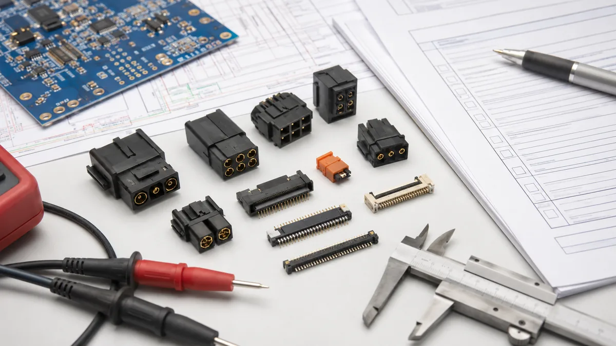
The best time to involve a connector supplier is after the boundary conditions are known but before the layout is locked. At that stage, the supplier can review whether an existing platform is suitable, whether pin loading should change, and whether a modified housing, terminal, or tooling route is needed. Waiting until a failure appears during validation usually leaves fewer options.
The uploaded project brief supports cautious LinkManu capability statements around tooling, stamping, injection molding, assembly, and inspection. It also supports mentioning that engineering work may include modeling, mold-flow review, terminal stress analysis, or signal-related review when the project requires it. These should be treated as project-dependent review paths, not as automatic steps for every connector.
Procurement teams should ask for the full drawing, not only a short product summary. Confirm polarity, pin numbering, latch direction, board footprint, material callouts, sample availability, inspection method, and any required certification or environmental evidence. For a deeper article focused specifically on power contacts, see how to choose the right power contacts.
Practical Sign-Off Checklist
Before releasing the PCB, use the checklist below to find missing decisions. A power and signal connector selection guide is only useful if it ends with evidence that engineering and purchasing can both verify.
- Drawing confirms pitch, mating height, pin numbering, polarity, footprint, and keep-out zones.
- Current path is reviewed with the intended pin assignment and expected loading pattern.
- Signal pins are checked for routing risk near power contacts, switching nodes, or noisy return paths.
- Termination process is compatible with the PCB assembly flow and inspection method.
- Housing and terminal materials are confirmed against temperature, humidity, chemical, and service conditions.
- Sample testing covers the real application risk instead of only a generic functional check.
- Supplier documentation is available before tooling or production release.
Conclusion: What to Confirm Next
The next step is not to collect more connector part numbers. Confirm the drawing, pitch, mating height, current rating basis, signal routing constraints, environment, material requirements, test documentation, and supplier capability. Once those inputs are visible, the shortlist becomes much easier to defend in both engineering review and purchasing review.
Frequently Asked Questions
What is the main goal of a power and signal connector selection guide?
It helps engineers verify current path, signal routing, mechanical fit, environment, and documentation before choosing a connector for a PCB.
Should power and signal pins use the same connector?
Only when the layout, heat rise, signal behavior, mating direction, and supplier evidence support a shared interface. Otherwise, separate connectors may reduce risk.
Which documents should be requested before sign-off?
Request the full drawing, material information, sample plan, derating or test evidence where applicable, and inspection criteria for production.
When should a supplier review happen?
After the electrical and mechanical boundary conditions are known, but before the PCB layout, tooling route, or production connector choice is frozen.
Send Your Connector Requirement
Share your drawing, BOM, PCB constraints, target application, and documentation needs. LinkManu can review connector fit, sample options, and RFQ readiness before final selection.

Technical content reviewed by LinkManu Engineering Team
Prepared by LinkManu Editorial Team for B2B connector engineers, sourcing teams, and product development projects. Updated 2026.