
Connector Engineering Guide
How to Disconnect Wire Connectors Without Hidden Damage
A wire connector should come apart because the lock has been released, not because enough force overcame it. That distinction matters in harnesses, control cabinets, machinery panels, vehicles, and energy equipment. If a technician pulls on the cable, twists a straight-pull design, or misses a secondary latch, the part may still pass a quick visual check while the contact system has already been stressed.
This guide explains how to disconnect wire connectors in a way that protects the connector and gives engineers a better RFQ checklist. The exact service method still depends on the connector drawing, supplier instructions, application environment, and whether the assembly is energized. When those inputs are missing, treat the disconnection method as an engineering item to confirm, not a field guess.
Start by Identifying the Locking Method
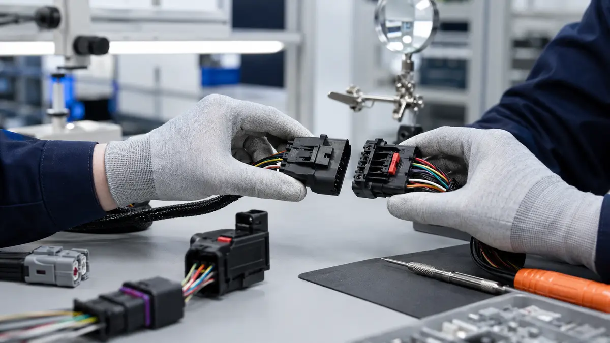
Before touching the connector, identify how the two halves are meant to separate. The housing shape, latch position, keying feature, coupling ring, backshell, and cable exit all give clues. If the connector is inside a tight assembly, first check whether the technician has enough access to press the release tab or rotate the coupling without side-loading the cable.
| Connector Style | Normal Release Action | Practical Risk | What to Confirm Before Service |
|---|---|---|---|
| Plastic latch connector | Depress the latch, then pull the housings apart in line. | A half-pressed latch can shave the locking feature or bend small terminals. | Latch direction, secondary lock position, and whether a release tool is required. |
| Push-pull connector | Release the sleeve or collar, then pull straight along the mating axis. | Side load from a bent cable can stress contact alignment during removal. | Required grip area, cable bend clearance, and operator access. |
| Bayonet connector | Rotate the coupling to the release position, then separate the pair. | Pulling before the ramps are released can mark the coupling and seal interface. | Correct rotation direction and whether the release feel is clear on samples. |
| Threaded connector | Unscrew the coupling ring before separating the connector halves. | Forcing a ring can damage threads and make the next mating unreliable. | Tool access, thread condition, and whether vibration has tightened the ring. |
Engineering check: If the release action is not obvious from the sample, add a service-access note to the drawing review. A connector that is easy to mate on the bench can still be difficult to disconnect after it is installed behind a bracket or inside a narrow cabinet.
A Safe Disconnection Sequence
The sequence below is intentionally conservative. It applies best to engineering samples, production harnesses, and maintenance work where the connector must remain reusable after inspection.
- Make the circuit safe first. Follow the equipment lockout or service procedure before handling electrical connections. If the application involves stored energy, high current, or control signals, do not treat the connector as a simple mechanical part.
- Clean the area around the connector. Dust, oil, coolant, adhesive residue, or ice can make a good latch feel stuck. Cleaning also prevents debris from entering the mating interface after separation.
- Support the connector housing. Hold the body or coupling area. Do not pull from the cable, wire bundle, or strain relief unless the supplier procedure specifically says that is the release point.
- Release every lock before pulling. Many wire connectors use a primary latch plus a secondary lock, terminal position assurance feature, or safety clip. If resistance stays high, stop and recheck the lock instead of increasing force.
- Separate in the intended direction. Pull straight for straight-pull designs, rotate only the coupling for bayonet or threaded styles, and avoid rocking unless the connector instruction allows it.
After separation, inspect both halves before remating. Look for scraped latch shoulders, bent contact tips, displaced seals, loose terminals, and cable jacket movement near the strain relief. A connector that feels loose after one disconnect should not be released into production without checking the drawing requirement and sample history.
What Forced Pulling Usually Damages
Forced disconnection often leaves subtle damage rather than an immediate open circuit. That is why procurement and quality teams should not accept “it still works” as the only inspection result after a difficult disconnect.
- Latch wear: A damaged latch can still click once, then loosen under vibration or repeated handling.
- Terminal movement: A pulled wire can shift a crimped terminal inside the cavity, creating intermittent contact under movement.
- Contact misalignment: Side force during removal can bend small signal contacts or reduce the consistency of the next mating.
- Seal disturbance: If the connector uses an environmental seal, twisting or dragging the housing can disturb compression and should trigger a sealing review.
- Thread or coupling damage: On threaded and bayonet styles, damaged mechanical features can make the connector feel assembled while the interface is not fully seated.
For basic push-in terminal release, the same principle applies: release the retention feature before pulling the conductor. LinkManu has a related guide on how to release a wire from a push-in connector, but industrial harness projects should still confirm the exact release method with the connector supplier and drawing.
How Procurement Should Specify Disconnect Requirements
If a connector will be disconnected during maintenance, production testing, module replacement, or field repair, the RFQ should say so. A supplier cannot judge the correct latch design, housing material, terminal retention, or seal structure from current rating alone. The safer question is: “How many times will this connector be handled, by whom, and in what installed position?”
When reviewing connector product options, include these items in the sourcing file:
- Connector family, drawing revision, pitch, pin count, mating height, and keying requirement.
- Cable specification, wire gauge, shield termination, bend direction, and strain relief requirement.
- Expected maintenance access, including whether a hand, tool, or fixture can reach the latch.
- Current rating, temperature range, vibration exposure, and environmental sealing requirement as project values to confirm from the drawing or test plan.
- Required documentation for insertion force, extraction force, terminal retention, temperature rise, hi-pot, salt spray, vibration, or other tests relevant to the application.
Supplier Review Before Production Release
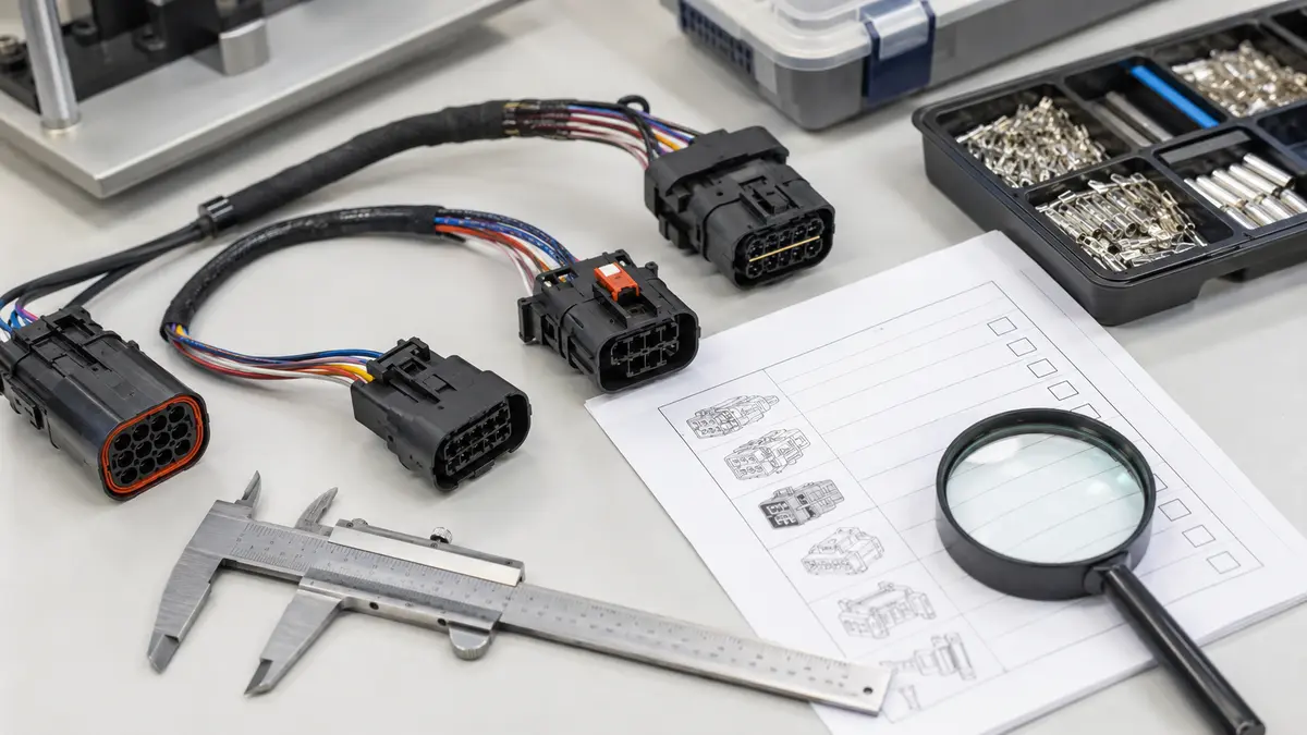
A disconnect problem is often a design-and-process issue, not only a technician issue. During supplier review, ask how the housing, latch, terminal, and assembly process are controlled. For custom connector or harness projects, the relevant process may include tooling, injection molding, stamping, assembly, and inspection before shipment. Which steps apply depends on the part, drawing, and RFQ scope.
Certifications such as IATF 16949 and ISO 14001 can support a process review, but they do not replace application-specific validation. For a connector that will be handled often, request sample reports or a proposed validation plan rather than a general capability statement. If a supplier cannot explain how the latch, terminal retention, and seal are checked, the disconnect method is not ready for production release.
Buyer judgment: The best time to discuss how to disconnect wire connectors is before the connector is frozen in the mechanical layout. Once the harness route, bracket, and service clearance are fixed, even a good connector can become difficult to release without damage.
Before You Approve the Final Drawing
Use the final drawing review to remove ambiguity. Confirm the release action, service clearance, mating direction, secondary lock position, label orientation, and inspection points after disconnection. If the design depends on a tool, name the tool or at least specify the tool-access envelope. If the assembly is expected to pass environmental or vibration testing after repeated service, define the test documentation needed before purchase order release.
The next step is practical: send the drawing, mating connector information, cable specification, target current rating, operating environment, and test documentation requirement together. That gives the engineering and sourcing teams enough context to judge whether the connector is serviceable, not just whether it can be connected once.
Frequently Asked Questions
How do you disconnect wire connectors?
Make the circuit safe, identify the latch or coupling style, release all locks, hold the connector housing, and pull or rotate only in the intended direction. Do not pull from the wires.
How do you take apart a wire connector?
Separate the plug and receptacle only after the locking feature is released. If the connector includes a secondary lock or terminal position feature, confirm whether it must be moved before separation.
How do you unclip a connector?
Press or lift the clip fully, then pull the housings apart in line. If the clip does not move cleanly, stop and check for a secondary lock, debris, or limited access.
How do you disconnect stubborn electrical connectors?
Clean the interface, support the housing, and use the correct release tool if required. Do not twist a straight-pull connector or add force until the locking method is confirmed.
Send Your Connector Requirement
Share your drawing, BOM, cable specification, target application, and test documentation needs. LinkManu can review connector fit, sample questions, and RFQ readiness before final selection.

Technical content reviewed by LinkManu Engineering Team
Prepared by LinkManu Editorial Team for B2B connector engineers, sourcing teams, and product development projects. Updated 2026.