
Engineering Guide
Power Contacts Connector Selection Guide
A power contacts connector selection guide should not start with a catalog photo. It should start with the load path, the housing, the termination process, and the evidence needed before a buyer approves samples.
In power connector projects, the contact is often the part that decides whether the assembly stays stable under continuous load. A housing can look correct, and the mating action can feel firm, but a weak contact choice may still create heat, voltage drop, fretting wear, or assembly variation. The practical question is simple: can this contact carry the intended current in the real connector body, with the real wire, PCB, enclosure, and operating environment?
Publishing note: This article treats specific current, voltage, temperature, pitch, plating thickness, and certification values as project checks, not as fixed claims. Those values should come from the customer drawing, supplier datasheet, sample report, or approved test file.
Start With the Failure Mode, Not the Part Number
Power contact failures usually show up as symptoms somewhere else: a warm housing, intermittent equipment operation, discoloration near a terminal, unstable voltage under load, or field service calls after vibration exposure. When the first review is only “does it fit,” these risks stay hidden until prototype testing or, worse, production use.
For engineering teams, the first judgment is whether the contact has enough margin in the actual assembly. Multiple loaded positions, limited airflow, nearby heat sources, board copper thickness, wire size, and enclosure material can all change the thermal result. A rating from a single contact condition is useful background, but it is not the same as proof for a dense connector in a finished product.
For procurement, the risk is different but just as real. A contact that is “close” in size may create a late redesign if insertion depth, retention force, plating, or termination geometry does not match the application. The lowest-risk RFQ is therefore not a request for a similar-looking terminal. It is a request tied to drawings, load conditions, mating details, and inspection records.
Selection Factors Engineers Should Confirm
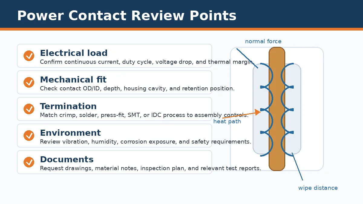
The safest way to compare power contact options is to separate the review into electrical, mechanical, process, environmental, and documentation checks. Each area can block the project even when the others look acceptable.
| Selection Area | Engineering Check | Procurement Risk | Evidence to Request |
|---|---|---|---|
| Electrical load | Confirm continuous current, duty cycle, voltage drop, and heat rise in the intended connector arrangement. | A catalog rating may not reflect all contacts loaded in the final housing. | Temperature rise report, application load profile, conductor and PCB details. |
| Mechanical fit | Check contact body diameter, cavity fit, insertion depth, retention feature, and mating wipe. | A visually similar contact can loosen, bottom out, or leave unstable contact force. | Section drawing, cavity drawing, sample measurement, insertion and extraction force data. |
| Termination method | Match crimp, solder, press-fit, surface-mount, or IDC design to the real assembly process. | Wrong tooling or process window can create high-resistance joints even with the right contact shape. | Process specification, tooling requirement, pull-force or section inspection plan. |
| Material and plating | Confirm base material, plating stack, and wear area against the environment and mating cycle need. | Unverified plating can pass incoming inspection but fail after corrosion, vibration, or repeated mating. | Material declaration, plating report, environmental test plan. |
| Quality control | Define what must be inspected before shipment and what must be tested during qualification. | Without traceable inspection, batch variation becomes hard to diagnose after assembly. | Inspection report, lot traceability, test records, change-control procedure. |
Electrical Review: Rated Current Is Only the Starting Point
The current rating is a starting point, not a purchase decision by itself. Engineers should ask how the contact behaves when the connector is fully populated, when neighboring positions carry load, and when the equipment reaches its normal operating temperature. A small increase in contact resistance can become meaningful when it appears at a power interface that runs for long periods.
The practical check is whether the supplier can explain the thermal path. Heat may leave through the contact body, wire, PCB copper, surrounding plastic, enclosure, or airflow. If any part of that path is weaker than assumed, the contact can run hotter than expected. For battery, industrial, and power distribution applications, ask for temperature rise evidence under conditions close to the real use case.
Short-duration peaks also need separate review. A contact may survive brief inrush or fault exposure only if the upstream protection, conductor size, and contact geometry are aligned. This is not a place for a generic promise. The acceptable condition should be written into the specification and verified by sample testing where the application requires it.
Mechanical Fit: Small Differences Can Change Contact Force
Mechanical fit is not limited to whether the contact enters the housing. The important checks are the contact’s working position, retention point, mating depth, wipe distance, and spring force after mating. If the contact stops early, sits too loose in the cavity, or mates at the wrong depth, the interface may look assembled while carrying current through a smaller or unstable contact area.
This is where sample-matching sourcing can become risky. If a buyer only sends a photo or a partial dimension, the supplier may find a candidate part that appears similar but does not match the original contact system. A better request includes the connector family, mating side, inner and outer contact dimensions, housing cavity details, terminal length, retention feature, mounting type, and any board or panel constraints.
For board-to-board power connectors, mating height and tolerance absorption deserve early attention. If the connector must absorb PCB assembly tolerance, vibration, or board misalignment, that requirement should be stated before sampling. Otherwise, solder joints or contact beams may be forced to absorb movement they were not designed to handle.
Termination Method Must Match the Factory Process
A good contact can still fail if the termination process is wrong. Crimp contacts need the correct tooling, wire preparation, barrel compression, and inspection method. Soldered contacts need a controlled heat profile so the joint forms without damaging nearby plastic or changing the spring behavior of the contact. Press-fit and surface-mount contacts need board design, hole control, or pad design that supports the intended current path.
For procurement, the key question is whether samples are made with the same process expected for production. Lab-built samples can be useful for form review, but they do not prove volume assembly stability. Ask whether the supplier can provide process notes, tooling requirements, inspection criteria, and the type of test report needed for qualification.
- Crimp contacts: confirm wire size, tooling, pull-force check, and crimp section inspection.
- Solder contacts: confirm heat exposure, solder joint access, cleaning requirement, and plastic temperature limits from the approved material file.
- Press-fit contacts: confirm PCB hole specification, insertion process, repair policy, and board damage risk.
- Surface-mount contacts: confirm pad layout, coplanarity, reflow profile, and heat spreading path.
- IDC contacts: confirm wire match and strand damage risk before using them in a power path.
Material and Plating Choices Are Application Decisions
Material and plating should be selected against the environment, mating frequency, normal force, and cost target. The uploaded project facts do not support fixed plating thickness or universal material claims, so those details should remain drawing-level requirements. What can be stated safely is that terminal material, plating, plastic material, and flame rating must be confirmed for the end application.
In a dry indoor product, the review may focus on stable contact resistance and assembly cost. In machinery, energy storage, outdoor equipment, or vehicle-related electronics, vibration, humidity, corrosion exposure, and thermal cycling may matter more. A buyer should not approve a lower-cost contact until the supplier explains how the material and plating choice fits the operating environment.
Engineering judgment: treat plating and material as controlled requirements, not optional cosmetic details. If the environment changes, the contact review should reopen.
Stamped, Machined, and Application-Specific Contacts
Stamped contacts often suit higher-volume projects where tooling, strip handling, and repeatable forming can control cost. Machined contacts are often considered when geometry, contact mass, lower tooling dependence, or tighter feature control is more important than piece-part cost. Neither route is automatically better. The right choice depends on contact geometry, production volume, qualification burden, and how quickly the design may change.
Application-specific power contacts are worth considering when a standard contact cannot meet the mechanical envelope, thermal path, retention feature, or assembly method. The decision should be made with the whole connector in mind. A terminal change can affect the housing cavity, plastic material, assembly sequence, test plan, and documentation package.
LinkManu’s related Power Connectors for DC and High-Current Interface Projects page is the most relevant product-family context for this topic. Use it as a category reference, then confirm the actual contact design against your drawing and application requirements.
Testing and Documentation to Ask For
A supplier conversation becomes more useful when the test request is specific. Instead of asking whether a contact is “reliable,” ask what evidence will be available for the load condition, environment, and assembly process. Company materials for the LinkManu factory source describe connector quality and testing capabilities, with some tests arranged through qualified outside resources when required. That wording matters: not every test is automatic for every project.
- Temperature rise review: confirm the contact and housing under the expected loading condition.
- Contact resistance check: measure before and after relevant mechanical or environmental exposure.
- Hi-pot or insulation review: confirm the connector does not compromise required insulation distances.
- Mating endurance review: check wear, contact force, and resistance after the intended use cycle.
- Vibration or shock review: use when the product environment can create micro-motion or intermittent contact.
- Corrosion or humidity review: use when the connector may face moisture, industrial atmosphere, or outdoor exposure.
For manufacturing confidence, the uploaded facts support referencing IATF 16949 and ISO 14001 as company certification references. They should be treated as process and management indicators, not as a promise that every connector automatically meets a specific end-product certification.
Supplier Capability Questions Before RFQ
The uploaded company facts support process capabilities including tooling, stamping, injection molding, assembly, and inspection before shipment. That is useful for power contact projects because terminal design and housing design often need to be reviewed together. The limitation is just as important: the exact process depends on the product type and RFQ scope.
| Question | Why It Matters | What to Send |
|---|---|---|
| Is this a new design, a sample match, or an approved drawing review? | The engineering route and risk level are different for each case. | Drawing, sample photos, mating part information, and target application. |
| Which connector family and mounting style are involved? | Wire-to-board, board-to-board, PCB, and battery formats create different contact constraints. | Connector family, board layout, wire details, panel or enclosure constraints. |
| What electrical and environmental conditions must be verified? | The test plan cannot be chosen safely without the real operating condition. | Current and voltage targets, duty cycle, ambient condition, vibration or humidity exposure. |
| What documentation is needed before approval? | Procurement may need more than samples to approve a production source. | Drawing file, material notes, inspection report, test report request, and packaging needs. |
If the project is still early, review the broader LinkManu product categories first. If the drawing is ready, the Contact LinkManu page is the better path for a technical pre-check before RFQ.
What to Include in a Power Contact RFQ
A useful RFQ should make the engineering constraints visible. Send the connector drawing, BOM, mating side, target application, expected load condition, wire or PCB details, contact dimensions, mounting style, termination method, material or plating requirements if already specified, and the documentation you need for approval.
Also state the commercial stage. A sample review, pilot run, and volume order should not be quoted as if they carry the same risk. If tooling may be required, clarify whether the design is still open to engineering adjustment or already frozen by the customer’s ECR process.
FAQ
What is the difference between a power contact and a signal contact?
A power contact is reviewed for current path, heat rise, contact force, and termination stability. A signal contact is usually reviewed more around signal quality, pitch, impedance, and fine mechanical control.
Can I choose a power contact by rated current only?
No. Rated current must be checked against the real housing, number of loaded positions, wire or PCB design, ambient condition, and duty cycle.
Is a similar-looking contact safe to use?
Only after dimensional, mechanical, material, and electrical checks. A small change in depth, retention, plating, or contact force can change the result.
What files should I send before asking for samples?
Send the drawing, BOM, mating connector information, load condition, operating environment, termination method, and any required test or inspection documents.
Send Your Connector Requirement
Share the drawing, BOM, target current and voltage, mating height or contact dimensions, termination method, operating environment, and required test documentation. LinkManu can review whether the project is ready for sample discussion or needs more engineering checks first.

Technical Review
Reviewed for LinkManu publishing by the LinkManu Editorial Team with engineering-focused checks for unsupported parameters, unsafe match wording, internal links, RFQ placement, and project documentation requirements.