
Cable Assembly Engineering Guide
Top 10 Electrical Specifications: Cable Assembly Wiring Harness Checklist
For a cable assembly wiring harness project, the top 10 electrical specifications are voltage rating, current capacity, temperature rise, insulation resistance, dielectric withstand, contact resistance, controlled impedance, shielding performance, crosstalk, and insertion loss or VSWR. The exact values should come from the customer drawing, application environment, connector datasheet, and agreed test plan rather than from a generic checklist.
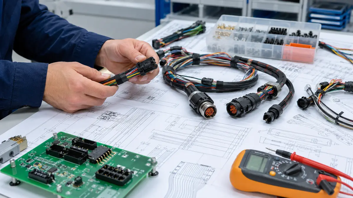
This guide explains how engineers and technical buyers can use the top 10 electrical specifications cable assembly wiring harness checklist during sourcing, design review, sample approval, and production handoff. It does not replace project-specific validation; instead, it helps you ask the right questions before the harness is quoted, built, or approved.
Why Datasheet Values Are Not Enough
A connector or cable may look suitable when each component is reviewed separately. The risk appears when those parts become a finished assembly: crimps, wire routing, bundle density, shield terminations, strain relief, overmolding, and the final operating environment all influence electrical performance.
Engineering note: Treat published component ratings as starting points. The finished cable assembly or wiring harness still needs an application-specific review and acceptance test plan.
What is a cable assembly? In practical sourcing terms, it is a set of conductors terminated with connectors and usually protected by jacket, overmold, sleeving, or strain relief. A wiring harness often includes multiple wires, branches, labels, clips, and connector interfaces. Both require electrical review because a drawing that defines only connector part numbers and wire colors may still leave critical performance questions unanswered.
The Top 10 Electrical Specifications to Confirm
The table below is a practical review framework. It is intentionally value-free: the required limits must be defined from the real circuit, operating conditions, and customer quality requirements.
| Specification | What to Define | Questions for Review |
|---|---|---|
| Voltage rating | Working voltage, expected transients, insulation system, spacing, and connector family limits. | Does the assembly have enough margin for the actual operating environment, not just steady-state voltage? |
| Current capacity | Conductor size, connector contact capacity, bundle condition, duty cycle, and allowable voltage drop. | Has the current requirement been reviewed for the whole harness path, including terminals and mated connectors? |
| Temperature rise | Allowed heat rise under load, insulation class, enclosure conditions, and nearby heat sources. | Will the selected wire, terminal, and connector remain within the approved thermal limit during use? |
| Insulation resistance | Minimum resistance after assembly, handling, environmental exposure, or agreed conditioning. | Is the test condition clearly stated for incoming inspection or production release? |
| Dielectric withstand | Withstand test method, duration, acceptance criteria, and any exclusions for sensitive circuits. | Does the finished assembly require a hipot or dielectric test before shipment? |
| Contact resistance | Measurement method at mated connector pairs, crimp quality, plating condition, and stability after handling. | Is contact resistance checked only at component level, or also after termination and assembly? |
| Controlled impedance | Target impedance, cable construction, connector transition, termination process, and inspection method. | For RF or high-speed data, has impedance been reviewed across cable, connector, and termination together? |
| Shielding performance | Shield type, coverage, drain wire or connector termination, grounding approach, and EMI environment. | Is shielding selected for the real noise source and system grounding strategy? |
| Crosstalk | Pair layout, separation from power conductors, twist or shield requirements, and routing constraints. | Could nearby power, switching, or signal lines interfere with sensitive circuits? |
| Insertion loss / VSWR | Frequency range, cable length, connector interfaces, acceptable loss, and test reporting needs. | For RF cable assemblies, will the supplier provide evidence from the agreed production test method? |
Power Circuits: Voltage, Current, and Temperature
Voltage, current, and temperature rise are closely connected. A drawing may identify wire size and connector series, but the engineering review should still confirm load profile, routing, bundling, ambient conditions, and whether the harness is exposed to movement, moisture, or contamination.
For power conductors, the review should include the full current path: conductor, crimp, terminal, connector contact, mating interface, and any intermediate splice. A weak point in any one of those locations can increase resistance and heat. That is why finished-assembly testing is often more useful than relying only on individual component data.
Procurement check: Ask the supplier to confirm which electrical tests are performed on prototypes, which are performed in production, and which results can be included in the shipment documentation.
Signal Circuits: Impedance, Shielding, and Crosstalk
Signal circuits need a different review mindset. Low-level sensor lines, communication pairs, and RF cable assemblies may be affected by routing, spacing, shield termination, connector transition geometry, and nearby power conductors. If these details are left open, the assembly may pass continuity testing while still performing poorly in the final equipment.
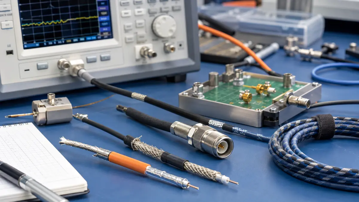
When comparing RF cable assembly manufacturers, focus less on broad promises and more on process control. Ask how they preserve cable geometry during stripping, crimping, soldering, shield handling, and final inspection. For impedance, insertion loss, and VSWR, the right requirement is the one defined by your system budget and confirmed by a test method both teams accept.
Connector Types That Need Specification Alignment
The types of electrical cable connectors used in harness projects vary widely, but the review logic is similar. Common families include circular connectors, RF coaxial connectors, D-sub and rectangular connectors, board-to-wire connectors, terminal and lug styles, and hybrid interfaces that combine power, signal, or optical paths.
Do not select a connector only because it mates mechanically. Confirm the electrical role, wire compatibility, termination process, sealing or strain relief needs, and how the connector will be tested after assembly. For custom or semi-custom projects, the review may also include tooling, stamping, injection molding, and assembly capability, especially when the connector interface and cable process must be developed together.
From Specification Sheet to Production Test Plan
A specification becomes useful only when it can be inspected and repeated. For a cable assembly or wiring harness, that means the drawing, BOM, inspection criteria, sample approval record, and production test plan should describe the same requirements in the same language.
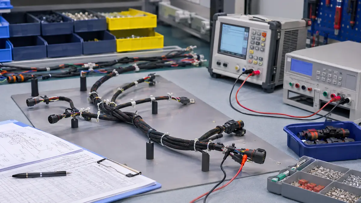
For cable assembly programs, LinkManu can review drawings, BOMs, connector choices, sample requirements, and production documentation needs. LinkManu source materials reference assembly, tooling, stamping, and injection molding capabilities, as well as IATF 16949 and ISO 14001 certification information. For product-family context, see Custom Cable Assemblies & Wire Harnesses Manufacturer | LinkManu.
Documentation Buyers Should Request
- Customer drawing and BOM revision used for quotation and sample build.
- Electrical test items, acceptance criteria, and test frequency for prototype and production stages.
- Crimp, solder, overmold, shield termination, and strain relief review records where applicable.
- First-article or sample inspection report tied to the approved drawing revision.
- Certificate or quality documentation required by the target industry or customer system.
Frequently Asked Questions About Cable Assembly Specifications
What are the top 10 electrical specifications for a cable assembly wiring harness?
The practical checklist includes voltage rating, current capacity, temperature rise, insulation resistance, dielectric withstand, contact resistance, controlled impedance, shielding performance, crosstalk, and insertion loss or VSWR. The required value for each item should be defined by the application and verified through the agreed test plan.
What is a cable assembly compared with a wiring harness?
A cable assembly is usually a terminated cable set with connectors and protective construction. A wiring harness often contains multiple wires, branches, clips, labels, and connector interfaces. In both cases, the finished assembly should be reviewed as a system rather than as isolated parts.
What types of electrical cable connectors are common in harness projects?
Common connector groups include circular, RF coaxial, rectangular, D-sub, board-to-wire, terminal and lug, and hybrid connector styles. The right choice depends on electrical load, signal type, mechanical fit, environment, assembly method, and inspection requirements.
How should I compare RF cable assembly manufacturers?
Ask how each supplier controls cable preparation, connector termination, shielding, inspection, and RF test reporting. For impedance, insertion loss, or VSWR, require project-specific limits and test records instead of assuming that catalog compatibility is enough.
Is there one universal standard for cable harnessing?
No single document covers every cable harness application. Most projects combine customer drawings, workmanship requirements, connector family requirements, industry-specific quality expectations, and application testing. The safest approach is to list the applicable documents in the drawing package and connect them to measurable inspection criteria.
Send Your Connector Requirement
Share your drawing, BOM, target application, or electrical requirements. LinkManu can review connector fit, sample options, documentation needs, and RFQ readiness before final selection.

Technical content reviewed by LinkManu Engineering Team
Prepared by LinkManu Editorial Team for B2B connector engineers, sourcing teams, and product development projects. Updated 2026.