
I/O Connector Selection Guide
SMA Connector Size: I/O Panel Selection Guide
SMA connector size is a practical design question, not just a catalog detail. For an I/O panel, the connector body, panel opening, nut clearance, PCB position, cable routing, and supplier drawing all need to agree before the enclosure is cut or the BOM is released.
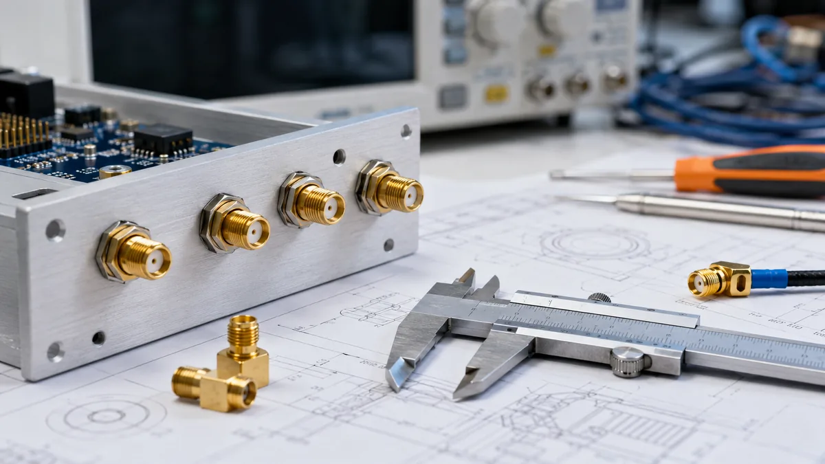
This guide explains how engineers and sourcing teams can review SMA connector dimensions for panel-mount, cable, and PCB interface projects without relying on assumptions. It focuses on the checks that should happen during drawing review, supplier confirmation, sample approval, and RFQ preparation.
Engineering note: Exact SMA connector dimensions, impedance targets, frequency limits, plating, sealing level, and mating-cycle requirements should be confirmed from the selected supplier datasheet and project drawing. This article is a selection and review guide, not a substitute for part-specific documentation.
Why SMA Connector Size Matters in I/O Panel Design
In a dense I/O panel, the connector is part of the mechanical system. A bulkhead connector may need wrench access, enough thread engagement for the panel stack, clearance from nearby USB, D-sub, circular, or power interfaces, and room for the cable bend path behind the panel.
The risk is highest when the team treats “SMA” as a single fixed outline. Two SMA connector types may share a familiar coupling interface, but still differ in body shape, rear termination, flange design, insulation structure, or mounting method. Those details can change how the part sits in a panel and how it lines up with the PCB or cable assembly.
For projects that combine RF, signal, and enclosure constraints, LinkManu recommends reviewing SMA connector size as part of the wider I/O Connectors for External and Panel Interface Projects selection process. The connector should be checked against the actual enclosure, assembly sequence, cable path, and documentation requirements.
Common Fit Risks to Catch Early
- Panel opening mismatch: the selected connector body, shoulder, gasket, nut, or flange does not match the panel cutout.
- Wrench clearance conflict: adjacent ports are close enough that assembly tools cannot reach the SMA connector after installation.
- PCB alignment drift: a board-mounted SMA connector does not align cleanly with the rear panel opening after tolerance stack-up.
- Cable routing pressure: the rear side of the connector forces a bend that adds stress to the cable or solder joint.
- Supplier drawing gap: the BOM references a part family, but the released drawing does not define the critical dimensions needed for inspection.
Key SMA Connector Dimensions to Review
The safest way to handle SMA connector dimensions is to treat them as a drawing review checklist. Instead of copying values from a generic online source, request the exact mechanical drawing for the selected part number and compare it with the enclosure, PCB, and cable model.
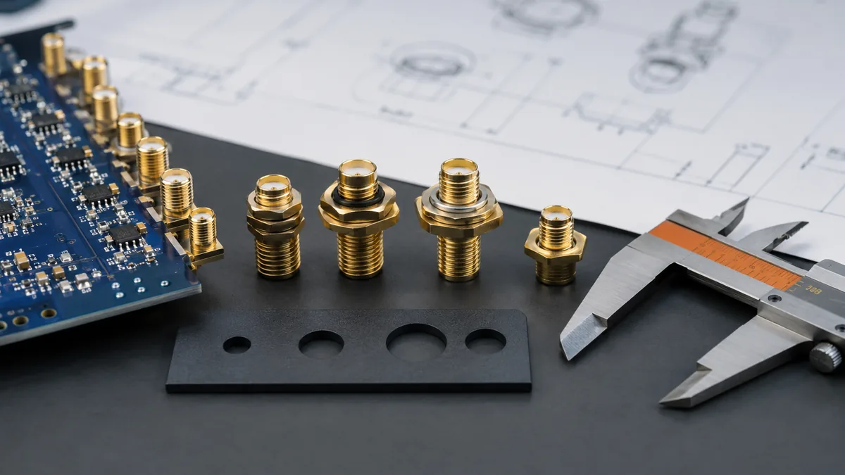
| Dimension Area | Why It Matters | What to Confirm Before Release |
|---|---|---|
| Panel opening and anti-rotation feature | Controls whether the connector seats cleanly and resists rotation during assembly. | Confirm the cutout shape, body shoulder, gasket face, and nut access against the supplier drawing. |
| Thread reach and panel stack | Determines whether the connector can be tightened correctly through the panel, coating, washer, and gasket stack. | Check the full installed stack instead of the bare metal panel only. |
| Body length behind panel | Affects clearance to PCBs, shields, cables, brackets, and other internal hardware. | Review the installed depth in the mechanical CAD model and prototype assembly. |
| Center contact position | Influences mating reliability and RF performance when paired with the selected cable or adapter. | Confirm the mating interface, gender, polarity, and inspection method with the supplier. |
| PCB footprint or edge-launch geometry | Links mechanical fit with soldering, impedance control, and board-to-panel alignment. | Match the connector drawing to the PCB stack-up, board edge, and panel reference plane. |
How to Compare SMA Connector Types
Different SMA connector types solve different interface problems. A cable plug, a bulkhead jack, a PCB receptacle, and an edge-launch connector should not be evaluated with the same checklist. The right comparison starts with mounting style and continues into assembly access, documentation, and validation needs.
| Connector Type | Typical Project Use | Size Review Focus | Supplier Questions |
|---|---|---|---|
| Bulkhead SMA jack | External RF port on an enclosure or I/O panel. | Panel cutout, nut access, gasket area, thread reach, and rear clearance. | Can you provide the installed drawing, recommended panel preparation, and inspection points? |
| Cable-mounted SMA connector | Coaxial cable assembly connected to an external or internal port. | Cable diameter, strain relief, rear body length, bend path, and mating interface. | Which cable, crimp, and assembly process is approved for this connector? |
| PCB-mounted SMA connector | Board-level RF interface inside instruments, gateways, or control hardware. | Footprint, board thickness, solderability, panel alignment, and ground transition. | Can the footprint and RF layout notes be reviewed before PCB release? |
| Edge-launch SMA connector | RF launch from the PCB edge to a cable or test interface. | Board edge geometry, stack-up, ground clearance, and connector-to-panel position. | What board stack-up and launch geometry does the selected part require? |
| Panel receptacle or flange style | Applications that need stronger mounting, sealing, or repeatable service access. | Flange envelope, screw access, sealing face, and assembly sequence. | Can samples be checked with the actual panel before production approval? |
Frequency and Impedance: Treat Them as Confirmation Items
Search results often mention SMA connector frequency range and impedance, but those details should not be transferred into a project BOM without checking the selected part. Connector geometry, dielectric structure, PCB launch, cable type, assembly process, and mating condition all influence real performance.
For that reason, the practical question is not only “what is the SMA connector size?” It is also: does this exact connector, in this exact mounting condition, meet the signal path requirement? The answer should come from supplier documentation, sample testing, or an engineering review tied to the project drawing.
Before quoting or sampling: send the target signal path, mounting method, panel drawing, PCB stack-up if relevant, cable requirement, and expected operating environment. The supplier can then confirm which SMA connector types should be reviewed and what documentation is needed.
Procurement Checks Before Releasing the BOM
Procurement risk usually appears when a part number is changed for cost, lead time, or availability after the mechanical design has already been frozen. A substitute may look similar in a catalog image while still requiring a different panel opening, nut clearance, rear keep-out area, or assembly process.
To reduce that risk, sourcing and engineering should define which dimensions are critical, which documents are required, and what must be rechecked if the part number changes. The goal is not to make every project slow. It is to make the approval path clear enough that a low-risk connector change does not become an enclosure rework problem.
Recommended BOM Release Questions
- Is the exact supplier mechanical drawing attached to the released BOM?
- Has the SMA connector size been checked against the final panel model and PCB layout?
- Are gender, polarity, mounting style, rear termination, and cable compatibility clearly defined?
- Does the drawing identify the dimensions that incoming inspection should verify?
- If an alternate supplier is allowed, what dimensions and performance items must be reapproved?
- Are samples required before production purchase, and who signs off the fit check?
Supplier Capability and Quality Documentation
SMA connector size control depends on process discipline as much as the drawing itself. LinkManu’s available company facts reference assembly, injection molding, stamping, and tooling capabilities, along with IATF 16949 and ISO 14001 certification references. For an RF or I/O connector project, those capabilities are relevant because small connector parts rely on repeatable tooling, controlled materials, and documented assembly processes.
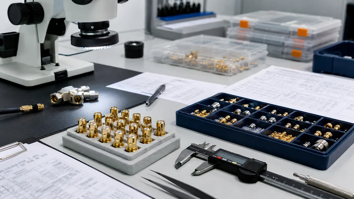
For sourcing teams, the strongest supplier conversation is specific. Ask how the connector body, contact, insulator, plating, assembly, and inspection steps are controlled for the selected part family. If the project needs a modified panel interface, custom cable assembly, or special documentation package, confirm that requirement during the RFQ stage rather than after the sample arrives. Teams comparing adjacent connector categories can also review the broader LinkManu product line before narrowing the final BOM.
| Supplier Review Area | Why It Helps | Document to Request |
|---|---|---|
| Mechanical drawing control | Keeps the approved SMA connector dimensions visible to engineering, purchasing, and inspection. | Part drawing, 3D model if available, and revision status. |
| Tooling and process capability | Supports repeatability when connector bodies, contacts, and insulators are produced in volume. | Process overview, tooling notes, and sample inspection plan. |
| Assembly and inspection | Reduces the chance that visual similarity hides a critical interface difference. | First article report, inspection records, and packaging or traceability information. |
| Quality system references | Helps buyers understand the supplier’s documentation and process-control framework. | Relevant certification records and project-specific quality requirements. |
Rugged I/O Environment Questions
When SMA connectors are used in outdoor equipment, industrial machinery, transportation hardware, or frequently serviced panels, mechanical size review should include environmental and handling conditions. A connector that fits in a clean prototype may still need additional review for sealing, vibration, repeated mating, torque access, cable support, and maintenance procedures.
- Sealing: Does the selected connector require a gasket, O-ring groove, sealed rear side, or special panel finish?
- Vibration: Should the coupling method, cable support, or locking approach be reviewed against the actual vibration profile?
- Repeated service: Will a connector saver, adapter, or replaceable cable assembly reduce wear on the panel interface?
- Cleaning and exposure: Are plating, sealing, and material choices suitable for the expected environment?
- Assembly sequence: Can the connector still be installed, tightened, and inspected after neighboring ports and cables are in place?
Conclusion
SMA connector size should be reviewed as part of the complete I/O interface, not as an isolated catalog term. The selected part must match the panel opening, PCB or cable path, mating interface, assembly method, and validation requirement. When those details are checked early, engineering and sourcing teams can avoid late enclosure changes, uncertain substitutions, and sample delays.
Before releasing a BOM, confirm the exact SMA connector dimensions from the supplier drawing, define the critical inspection points, and align the part selection with the intended environment. For connector projects that involve RF ports, external panels, custom wiring, or documentation requirements, Contact Engineering Support for a structured project review before final selection.
Frequently Asked Questions
Are there different sizes of SMA connectors?
Yes. SMA connector sizes can vary by mounting style, body shape, rear termination, flange design, panel hardware, and internal construction. Always check the exact part drawing instead of assuming that all SMA connector types share the same installed envelope.
What SMA connector dimensions should be checked first?
Start with the panel opening, thread reach, nut or flange clearance, rear body depth, mating interface, and PCB or cable termination area. These dimensions usually decide whether the connector can be assembled and serviced correctly.
Can one SMA connector be replaced with another similar-looking part?
Only after engineering review. Similar-looking connectors may differ in mechanical envelope, contact design, cable termination, sealing method, or performance documentation. Any alternate part should be checked against the drawing, sample, and project requirements.
How should frequency requirements be handled during SMA selection?
Treat frequency and impedance as part-specific confirmation items. Share the target application, cable or PCB launch condition, and test expectations with the supplier, then request the documentation needed for the selected connector.
Send Your Connector Requirement
Share your drawing, BOM, target application, or technical requirements. LinkManu can review connector fit, sample options, documentation needs, and RFQ readiness before final selection.

Technical content reviewed by LinkManu Engineering Team
Prepared by LinkManu Editorial Team for B2B connector engineers, sourcing teams, and product development projects. Updated 2026.