
Board-to-Board Connector Engineering
High Speed Board to Board Applications: Selection Checks Before PCB Release
A board stack can pass a mechanical fit check and still become a problem during signal validation. In high speed board to board applications, the connector, PCB launch, mating height, ground return path, and assembly tolerance need to be reviewed together before the layout is frozen.
The practical question is not “which connector is fastest.” It is whether the selected board-to-board connector can fit the drawing, support the intended channel budget, survive the assembly tolerance, and come with enough documentation for the customer’s validation plan.
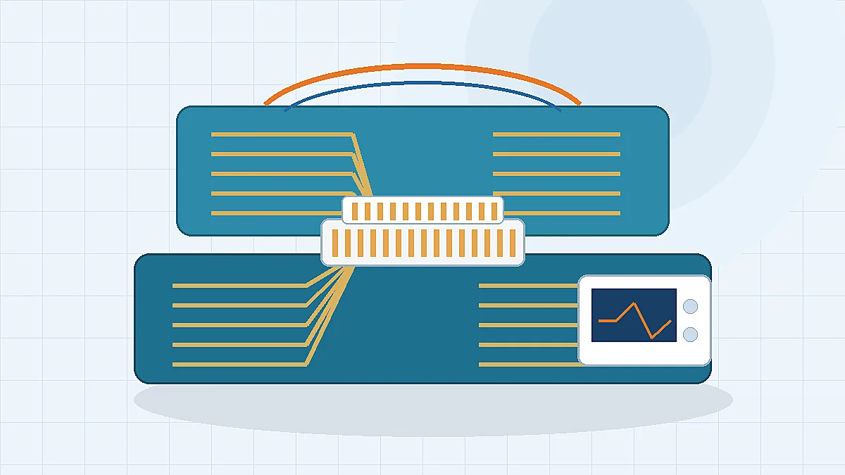
Engineering takeaway: confirm the drawing, pitch family, mating height, pin map, PCB stack-up, current paths, environmental exposure, and required SI documentation before moving from sample request to production release.
Start With the Channel, Not the Connector Catalog
For high-speed differential links, a connector is part of the signal channel. The launch pads, contact geometry, return path, and nearby lanes can change the result seen at the receiver. A catalog part number may be useful for the first discussion, but it does not replace a review of the customer’s stack-up, routing constraints, and protocol requirement.
Engineers should separate three inputs early: what the protocol or system validation plan requires, what the PCB layout can physically support, and what the supplier can document for the selected connector. Industry references such as IEEE 802.3 and SNIA SFF specifications are useful for understanding high-speed system expectations, but they should not be treated as a blanket performance promise for any connector family.
Procurement teams can reduce rework by asking one practical question before price comparison: can the supplier review the drawing and explain what must be confirmed before the sample is considered suitable for validation? If the answer is only a datasheet screenshot, the sourcing decision is still incomplete.
Where Board-to-Board Choices Create Project Risk
LinkManu’s Board-to-Board Connectors for Compact PCB Interconnects page is a suitable starting point for product-family review, but the article-level decision should stay project-specific. Pitch, pin count, stack height, terminal structure, and retention features must be checked against the drawing and the end-use environment.
| Selection Area | Engineering Risk | What to Confirm Before Sample Approval |
|---|---|---|
| Pitch and lane spacing | Higher density can reduce board area, but it may tighten PCB fabrication and alignment tolerance. | Confirm the pitch family against the layout, assembly capability, mating height, and signal budget. |
| Pin count and pin map | A pin count that fits the signal list may still lack enough ground returns or power contacts. | Review differential pairs, grounds, power pins, low-speed control lines, and reserved positions together. |
| Mating height | A taller stack can solve component clearance but may increase mechanical leverage under shock or vibration. | Check board spacing, keep-out zones, airflow, enclosure tolerance, and insertion direction. |
| PCB launch | Pads, vias, and trace transitions near the connector can create reflections or lane-to-lane coupling. | Ask whether a footprint, 3D model, or SI support file is available for the selected design stage. |
| Environment and handling | Vibration, repeated service access, contamination, and temperature cycling can change contact stability. | Define the test plan early instead of assuming a standard sample covers the final use case. |
Uploaded source materials list board-to-board reference examples such as 66H3 with 2.54 mm pitch and 06-100 pin options. Those values should be used as reference points for discussion, not as automatic fit guarantees. The final selection still depends on the customer drawing, stack-up, and validation requirement.
Use Floating Connectors Only When the Tolerance Problem Is Real
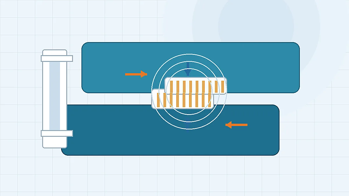
Floating designs are helpful when the board stack has placement tolerance, thermal movement, vibration, or enclosure-driven misalignment. They are not a shortcut for poor datum control. If the assembly can be controlled with a rigid connector and stable fixtures, adding float may create unnecessary cost, height, or sourcing complexity.
For projects that do need tolerance absorption, LinkManu can review Floating Board-to-Board Connectors within the evidence scope of the uploaded materials. The 66A2 and 66C8 references are listed as fine-pitch floating board-to-board options in the source package, but the usable float range, mating force, contact stability, and signal behavior must be confirmed against the project drawing and sample plan.
The procurement check is simple: ask what misalignment the design must absorb, where that movement comes from, and how the sample will be tested. Without those three answers, “floating” becomes a product label rather than an engineering decision.
Validation Documents to Request Before Production
A sample by itself does not prove readiness for high speed board to board applications. The buyer needs enough documentation to connect the connector choice to the customer’s PCB, test fixture, and release gate. Some items may be provided by the supplier, while others may be generated by the OEM during system validation.
| Document or Test Item | Why It Matters | Supplier Question |
|---|---|---|
| Customer drawing and mating interface review | Confirms pitch, height, envelope, keep-out zones, and mating direction before samples are selected. | Can the engineering team review the drawing before quoting the final configuration? |
| 3D model or mechanical file | Helps check enclosure clearance, board spacing, and assembly interference before tooling decisions. | Is a model available for the proposed connector family and mating height? |
| Signal integrity support data | Gives the system team a basis for channel review instead of relying on a mechanical datasheet only. | Can SI simulation, S-parameter support, or layout guidance be scoped for this project? |
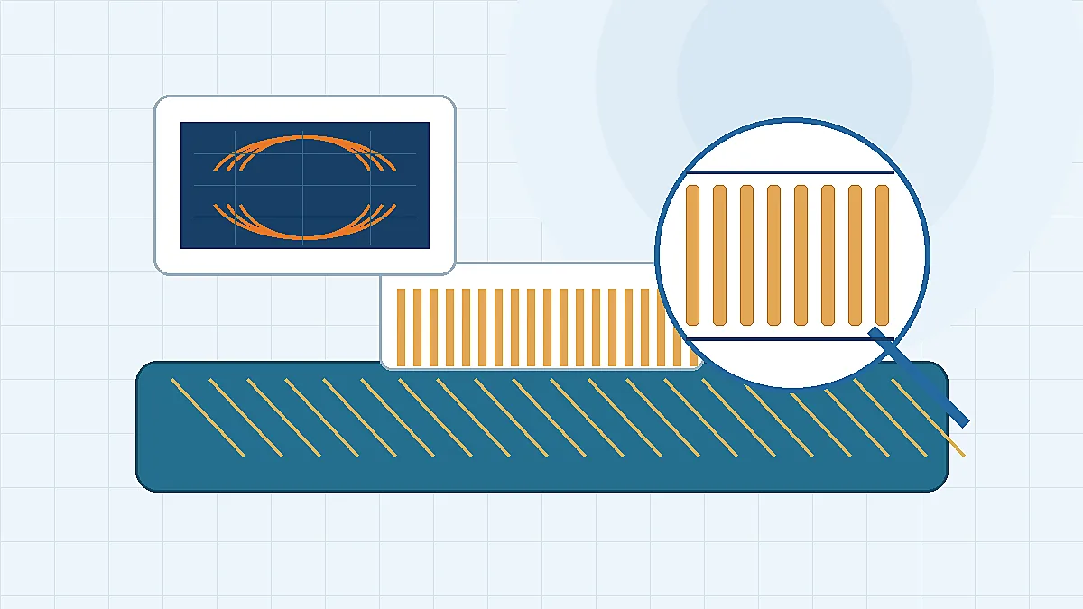
| TDR, eye-diagram, or coupon test plan | Checks whether the connector and PCB transition meet the customer’s validation threshold. | Which test data is available now, and which tests need to be arranged for this build? |
| Material, plating, and environmental test records | Reduces risk when the design faces heat, humidity, vibration, repeated mating, or special compliance needs. | Which reports are standard for the product, and which require project-specific testing? |
Company materials describe engineering support that may include Pro-E modeling, Moldflow analysis, ABAQUS terminal stress analysis, SI simulation, inspection before shipment, and outsourced testing when required. These should be scoped per RFQ. Do not assume every step is included unless the quote or project plan says so.
RFQ Inputs LinkManu Needs for a Useful Review
A useful RFQ should give the supplier enough context to judge feasibility, not just enough information to return a unit price. For high-speed board-to-board work, send the drawing, mating height target, pitch preference, pin count, pin map, PCB stack-up, target protocol, power/current paths, operating environment, expected sample quantity, and required test documentation.
If the design is replacing an existing connector, include the existing drawing or mating interface, but avoid assuming drop-in compatibility until the dimensions and test requirements are checked. If the design is new, define the board spacing and validation gate first; that prevents the sample discussion from drifting into catalog browsing.
The next step is a drawing-based review. Confirm the connector family, pitch, mating height, tolerance condition, signal requirement, and documentation package before locking the PCB release or committing to volume tooling.
FAQ: High-Speed Board-to-Board Connector Selection
What makes a board-to-board application high speed?
It becomes high speed when the connector transition can affect channel margin. The threshold depends on the protocol, rise time, PCB launch, and validation budget.
Can a standard board-to-board connector work in a high-speed design?
Sometimes. It must be checked against the layout, ground return path, mating height, and the customer’s SI validation plan.
Does smaller pitch always improve signal integrity?
No. Finer pitch may save space, but it can tighten fabrication, assembly, and inspection limits. The right pitch depends on the full board stack.
When should I choose a floating board-to-board connector?
Choose floating when the assembly has a defined misalignment or tolerance problem. Confirm the float range, mating force, and signal behavior with samples.
What should I send for a connector RFQ?
Send the drawing, mating height, pitch, pin count, pin map, PCB stack-up, target protocol, environment, and required test documents.
Send Your Connector Requirement
Share the drawing, board spacing, pitch target, pin map, environment, and validation documents needed for your high-speed board-to-board project. LinkManu can review the fit and identify what must be confirmed before samples or production release.

Technical content reviewed by LinkManu Engineering Team
Prepared by LinkManu Editorial Team for B2B connector engineers, sourcing teams, and product development projects. Updated 2026.