
Engineering Selection Guide
Amplifier Connector Types: I/O Selection Guide for Engineers
Searching by connector name is a useful starting point, but it does not settle an amplifier I/O decision. The selection has to match the panel drawing, PCB position, termination process, electrical role, field wiring, and operating environment. For sourcing teams, the safest sequence is to define those conditions first and compare connector families second.
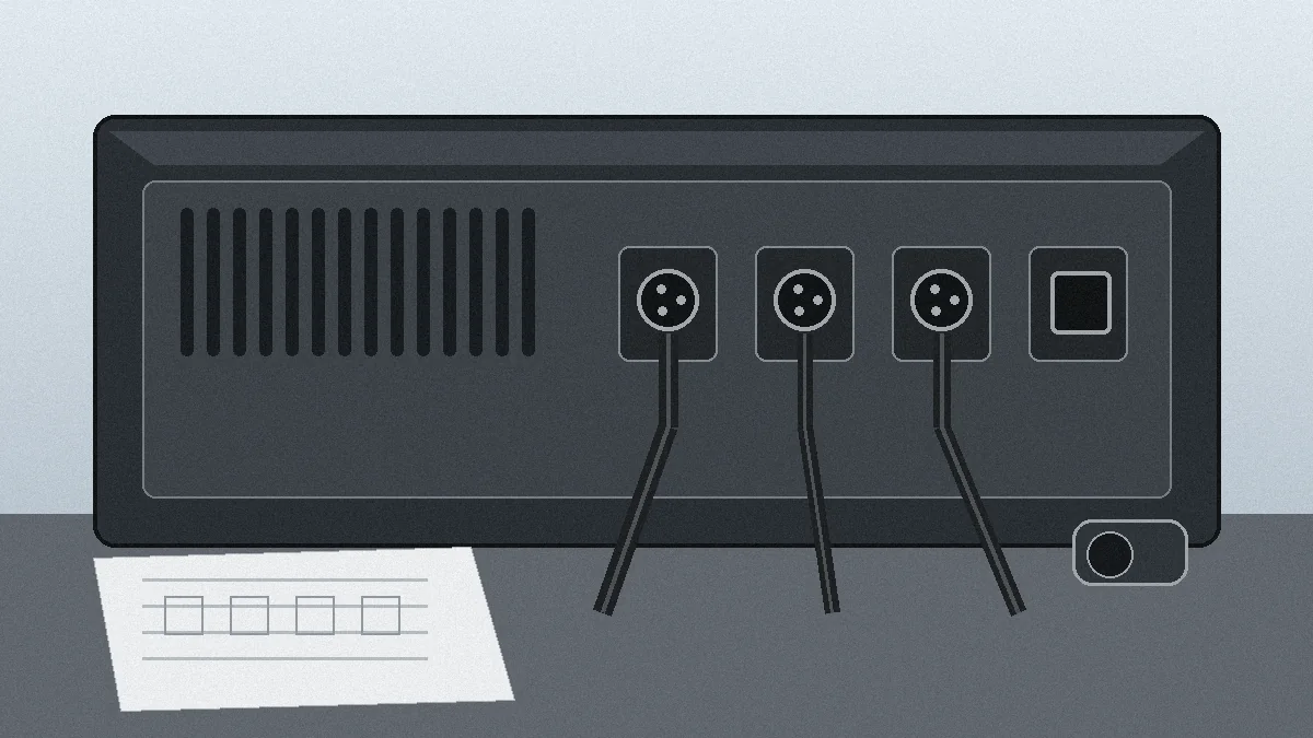
Start With the Amplifier Interface, Not a Connector Catalog
A catalog can tell you which families exist. It cannot tell you which one fits a specific chassis. Before a supplier comparison begins, the team should identify the connector location, panel opening, PCB relationship, cable routing, and the electrical function assigned to each contact. A family that looks correct can still create assembly or fit problems if the panel and PCB constraints were not checked together.
What the drawing should settle first
| Review item | Engineering or sourcing check |
|---|---|
| Panel geometry | Confirm the cut-out, panel thickness, mounting method, orientation, and keep-out space before choosing a receptacle footprint. |
| PCB relationship | Confirm PCB-to-panel offset, connector orientation, footprint, and internal clearance so the interface is not selected independently of the board layout. |
| Electrical role | Separate speaker output, signal, control, ground, and any other functions on the drawing; then ask the supplier to confirm the required ratings from approved documentation. |
| Termination and cable | Define the cable construction and production termination method. A mechanically suitable panel connector may still be unsuitable for the planned assembly process. |
| Service conditions | List the required mating life, vibration, moisture, dust, temperature, and handling conditions as project requirements rather than assuming a connector style meets them. |
Procurement rule: if a requirement is not on the drawing, specification, BOM, sample record, or test requirement, treat it as an item to confirm—not as an assumed connector capability.
How to Compare Amplifier Connector Types Without Over-Specifying
Amplifier panels may use different interface categories for speaker output, balanced or unbalanced signal paths, control connections, and fixed wiring. The useful question is not which family is universally “best.” It is which interface can be documented against the project’s mechanical, electrical, assembly, and service constraints.
Common categories and the decision each one triggers
- Locking speaker-style interfaces: evaluate them for speaker-output paths only after the project team defines the required electrical load, cable construction, locking behavior, panel mounting, and mating conditions.
- XLR-type interfaces: when considered for signal I/O, confirm the actual grounding and shielding approach, panel mounting, PCB or wire termination, and the supplier documentation for the selected part.
- RCA-style and phone-jack interfaces: compare panel density, cable strain, board placement, grounding, and service access. Do not assume a familiar form factor automatically satisfies noise or durability requirements.
- Terminal-block interfaces: useful where the project calls for field or fixed wiring, but the drawing should define conductor handling, retention, access, and strain-relief expectations.
- Hybrid or project-specific I/O: consider this path when a standard interface does not fit the required signal grouping, mounting envelope, or assembly plan. Customization should start with feasibility review rather than a promise of equivalence.
For broader panel-interface context, LinkManu’s I/O Connectors for External and Panel Interface Projects page describes the product family that can be reviewed against mechanical and electrical requirements. That scope does not mean every amplifier connector style or every performance requirement is automatically supported.

The Risk Is Usually an Unverified Requirement, Not the Connector Name
Most sourcing problems begin when a requirement is implied instead of documented. A connector may match the visible shape and still differ in termination, retention, environmental protection, contact system, or mounting geometry. Once the enclosure and PCB are released, changing the interface can affect more than the component line item.
That is why the supplier review should focus on evidence. Ask what drawing, datasheet, sample comparison, or test record supports the proposed selection. If a replacement or compatible alternative is being considered, provide the original part number or sample and request a dimensional and performance comparison. The conclusion should remain “candidate for review” until the project team approves the evidence.
LinkManu scope: current company materials support review of I/O and rectangular connector projects against mechanical and electrical requirements. They also list tooling, stamping, injection molding, and assembly capabilities. Whether any of those processes apply to a particular amplifier interface depends on the product design and RFQ scope.
Questions that should be resolved before release
- Is the panel opening frozen, or can the connector footprint still change?
- Does the PCB position force a specific orientation or termination method?
- Which electrical values must be confirmed from the customer specification or approved supplier documentation?
- What mating, retention, vibration, moisture, dust, or temperature conditions must the interface be reviewed against?
- Which test items are required by the project, and who is responsible for providing the corresponding evidence?
- If an alternative is proposed, what dimensions and performance characteristics must match before sampling can begin?
Prepare the RFQ Around Evidence the Supplier Can Review
A useful RFQ lets engineering evaluate the whole interface rather than guess from a connector photo. Send the documents that define fit, function, and production constraints, and mark unknown parameters as open questions instead of filling them with typical values.
| RFQ input | Why it matters |
|---|---|
| Dimensioned drawing or 3D data | Provides the panel opening, connector envelope, PCB relationship, mounting details, and keep-out areas needed for fit review. |
| BOM and interface definition | Shows the plug, receptacle, cable assembly, accessories, and the function allocated to each connection. |
| Application requirements | Defines the electrical, mechanical, environmental, and lifecycle conditions that require supplier confirmation. |
| Reference part or sample | Gives the supplier a basis for comparison when the project is evaluating a compatible alternative or a redesigned interface. |
| Required validation scope | Clarifies which checks or tests the project expects. Company materials indicate testing may be performed or arranged depending on the requirement; the exact scope should be agreed for the project. |
If you need a broader view of LinkManu’s connector categories before preparing the RFQ, see LinkManu Products. For a project-specific drawing or sample review, use Contact Engineering Support.
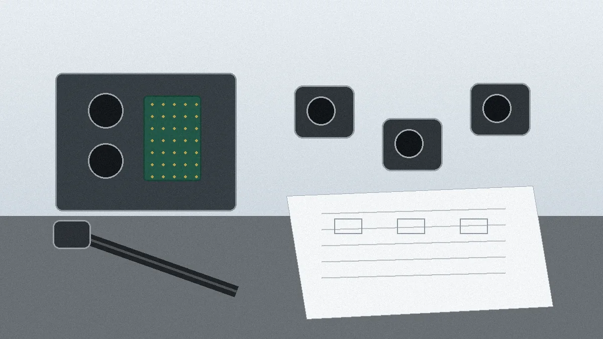
From Shortlist to Sample Review
Once the requirements are documented, narrow the shortlist and verify fit with the actual assembly context. Request the mating parts and relevant accessories needed for the intended installation. Check panel clearance, PCB alignment, cable routing, locking or retention behavior, and the production termination method before the footprint is treated as final.
If the project needs a non-standard I/O interface, start with the mechanical envelope and functional allocation. Company materials list design engineering support and manufacturing processes such as mold development, injection molding, stamping, assembly, and inspection, but the applicable process route depends on the connector design and RFQ scope. Project-dependent analysis tools may also be available; the specific modeling, simulation, and test plan should be confirmed for the project rather than assumed.
Next step: confirm the drawing, panel cut-out, PCB position, connector orientation, termination method, electrical requirements, operating environment, mating requirement, validation documentation, and supplier capability before approving an amplifier I/O connector.
Frequently Asked Questions About Amplifier Connector Types
How do I identify the correct amplifier connector type?
Start with the panel drawing and electrical function. Confirm mounting, PCB position, cable and termination, required ratings, environment, and mating conditions before comparing connector families.
Which amplifier connector type is best for a speaker output?
There is no universal best choice. Define the required load, cable, locking or retention method, panel geometry, mating conditions, and validation evidence, then compare suitable speaker-output interface candidates.
What should I send a connector supplier for review?
Send a dimensioned drawing or 3D data, BOM, interface functions, application requirements, validation needs, and any reference part number or sample being compared.
Can LinkManu review a custom amplifier I/O interface?
LinkManu materials support review of I/O and rectangular connector projects. Custom tooling or manufacturing steps may be considered when the design and RFQ scope support them; feasibility should be confirmed before commitment.
How should a compatible alternative be evaluated?
Treat it as a candidate, not a guaranteed replacement. Compare the drawing, sample, mounting geometry, termination, required performance, and project validation evidence before approval.
Send Your Connector Requirement
Share your drawing, BOM, target application, reference part, sample details, or open engineering questions. LinkManu can review RFQ readiness and the connector requirements that still need confirmation.