
How Do You Choose a Terminal Block Connector?
Choose from the application backward: define the conductor, mounting envelope, termination process, operating environment, and evidence required before comparing catalog parts.
Direct answer: How do you choose a terminal block connector? Start by fixing the wire range, circuit requirement, mounting method, available space, wire-entry direction, assembly process, environment, and documentation needs. Then compare candidate drawings and supplier evidence. Current rating and pitch alone are not enough to approve a part.
Start with the application boundary, not a catalog filter
A terminal block can match a schematic and still fail the mechanical review. The housing may block a harness bend, the wire entry may face an inaccessible panel wall, or conductor tension may load the PCB connection. In industrial equipment, vibration, thermal cycling, contamination, and maintenance access also change what “fits” means.
Write down the installation conditions before opening a supplier catalog. The Industrial Equipment Connector Solutions page shows the broader system context LinkManu uses when discussing connector projects. For this selection, the practical risk is approving a part before the enclosure, wiring route, and assembly sequence are settled.
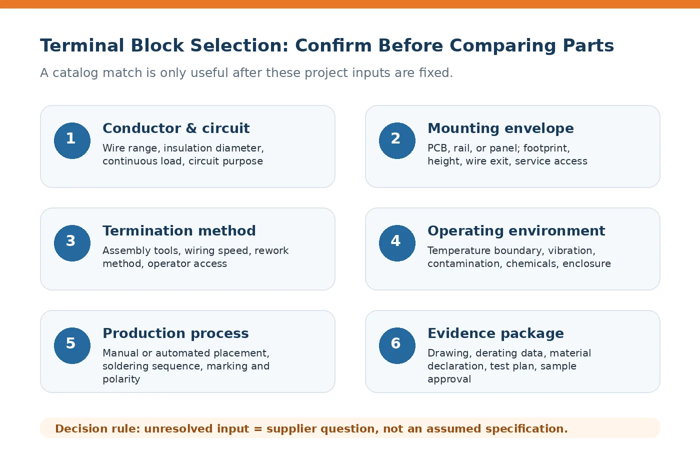
Freeze six inputs before comparing terminal blocks
Use the following items as RFQ questions when a drawing or application specification does not provide the answer. An unresolved value should remain open; it should not be replaced by a catalog assumption.
| Selection input | What engineering should confirm | Approval risk if omitted |
|---|---|---|
| Conductor and circuit | Accepted conductor range, insulation diameter, circuit purpose, and required continuous load under the actual installation condition. | A wire may not enter, clamp, or remain within the intended operating boundary. |
| Electrical spacing | Required insulation performance, dielectric test expectation, creepage, clearance, and any application-specific derating basis. | A dimensional match may still be unsuitable for the end-equipment requirement. |
| Mounting envelope | PCB, rail, or panel mounting; footprint; overall height; pole count; ganging; wire exit; and service clearance. | The part can interfere with the enclosure, adjacent components, or field wiring. |
| Operating environment | Temperature boundaries, vibration expectation, humidity, contamination, chemical exposure, and enclosure conditions. | Material, retention, or clamping choices may be based on the wrong environment. |
| Assembly process | Manual or automated placement, soldering sequence, required tools, operator access, marking, polarity, and rework method. | The connector may add labor, create placement errors, or obstruct soldering. |
| Evidence and approval | Drawing revision, derating data, material declaration, test plan, sample requirement, and compliance documents relevant to the project. | Procurement may compare quotations that do not cover the same technical scope. |
Match the termination method to the wiring process
The termination style affects operator steps, tooling, service access, and the conductors that can be used. Do not select it only from a preference such as “tool-less” or “familiar to technicians.” Confirm how the wire is prepared, inserted, checked, removed, and reworked on the real assembly line.
Screw clamp
Check whether production already controls the tightening process and whether field access allows the required tool. The purchasing question is not only unit price; include the assembly and inspection step.
Spring-actuated connection
Confirm the actuation method, conductor preparation, and technician access. Ask how the connection is opened during service and whether the selected wire construction is accepted.
Push-in connection
Verify which conductor constructions can be inserted directly and when a ferrule or preparation step is needed. A fast insertion claim has little value if wire preparation becomes the bottleneck.
Insulation displacement
Confirm the permitted conductor and insulation range and the required insertion tooling. Treat it as a process-specific option rather than a universal substitute for stripped-wire termination.
Check mounting and production fit on the actual assembly
PCB-mount, DIN-rail, and panel-mount terminal blocks solve different installation problems. The chosen configuration should be reviewed in the enclosure model or drawing, including wire bend space, neighboring components, fastening access, and the force applied during field wiring. Heavy conductors can transfer load into the housing, solder joints, or rail attachment if strain is not managed.
Production adds another constraint. For automated placement, confirm orientation features, polarity marking, pickup conditions, packaging, and the process used after placement. For manual wiring, check terminal numbering, actuator visibility, tool angle, and the ability to inspect a completed connection. During soldering, review body height and spacing around nearby components rather than assuming the PCB footprint settles the process.
Use supplier capability as evidence, not as a slogan
A supplier review should connect each capability to an open project risk. Uploaded LinkManu source material supports manufacturing capabilities that include tooling, injection molding, stamping, and assembly. It also describes project-dependent engineering support using 3D modeling, Moldflow analysis, terminal stress analysis, and signal-integrity simulation. These steps should be requested only when relevant to the product and RFQ scope; they are not automatic for every terminal block project.
- Ask who owns the drawing review and how design changes are recorded before sampling.
- Confirm whether electrical, environmental, and mechanical tests are performed directly or arranged through another qualified resource.
- Request the certificates and declarations required by your end application, then verify their scope and validity.
- Clarify whether customization changes the mold, terminal, plating requirement, marking, packaging, or assembly process.
- Agree on sample quantity, approval criteria, and the documents that will accompany first articles.
For projects that need a modified interface or new tooling, use the Custom Connector Support process to structure the review. The Engineering & Quality page provides the relevant capability and quality-system context.
Prepare an RFQ package that reduces assumptions
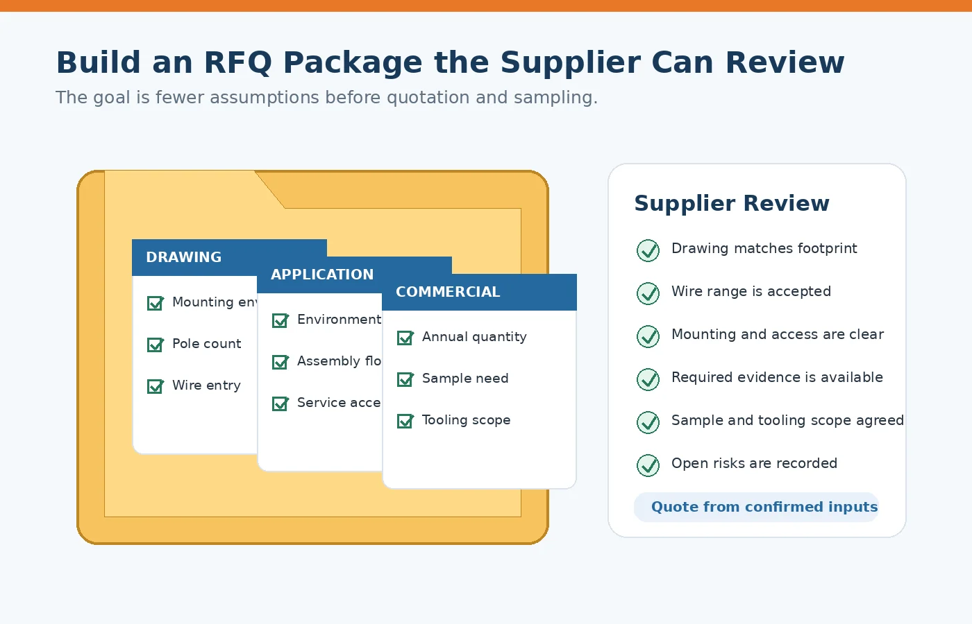
A quotation is easier to compare when every supplier receives the same boundary conditions. The package does not need to be perfect, but unknown items should be labeled as open decisions.
| RFQ item | Priority | What it prevents |
|---|---|---|
| 2D or 3D drawing with mounting and interface limits | Required | Quoting a part that fits electrically but not mechanically. |
| Pole count, wire arrangement, and conductor details | Required | Wrong housing length, wire-entry assumption, or termination choice. |
| Application environment and assembly description | Required | Material and process decisions based on bench conditions. |
| Target annual quantity and sample requirement | Required for commercial review | Misaligned tooling, packaging, and manufacturing assumptions. |
| Compliance, declaration, and test-document list | Project dependent | Late discovery that required evidence is outside the quotation. |
| Known tooling scope or approval budget | Recommended for custom work | Repeated redesign after the commercial boundary is set. |
A practical decision sequence
- Confirm the drawing boundary. Fix footprint, profile, mounting, pole count, wire entry, and maintenance access.
- Confirm the conductor and circuit. Record wire construction, accepted range, insulation diameter, circuit purpose, and operating requirement.
- Select the termination process. Compare preparation, tools, insertion, inspection, removal, and rework on the intended line.
- Review the environment. Send the supplier the actual temperature, vibration, humidity, contamination, chemical, and enclosure conditions that matter.
- Request evidence. Match drawings, declarations, test documentation, samples, and certificates to the project—not to a generic supplier checklist.
- Close open items before approval. Record unresolved parameters, supplier responses, drawing revisions, and sample acceptance criteria.
The next step is concrete: send the drawing, conductor details, mounting envelope, assembly method, environment, annual quantity, and required test documentation for review. Do not release the part from a catalog comparison alone.
Frequently asked questions
How do I size a terminal block correctly?
Start with the accepted conductor range and insulation diameter, then verify the circuit requirement under the actual enclosure condition. Cross-check the supplier drawing and derating information before approval.
Are terminal blocks with the same current rating interchangeable?
No. Pitch, profile, mounting, wire range, spacing, material, termination, and documentation can differ. Compare drawings and application requirements line by line.
What should I send with a terminal block RFQ?
Send the drawing, pole count, wire details, mounting orientation, environment, assembly method, annual quantity, sample need, and required compliance or test documents.
When is a custom terminal block worth reviewing?
Review customization when the standard part misses the envelope, wire exit, marking, pole configuration, material requirement, or production process. Confirm tooling and approval scope before design work starts.
Send your connector requirement
Share the drawing, conductor details, mounting limits, target application, annual quantity, and required documentation. LinkManu can review fit, open technical questions, sample scope, and RFQ readiness before selection.

LinkManu engineering content
Written for engineers and technical buyers preparing connector drawings, supplier questions, samples, and RFQ documentation.