
Connector Selection Guide
Internal IO Connectors Selection Guide: How to Choose for Your Application
An internal IO connectors selection guide should start with the product layout, not with a catalogue filter. Inside equipment, one connector choice can affect board spacing, cable routing, latch access, signal path, service handling, and purchasing risk. A part that looks acceptable on a datasheet can still create rework if the cable exits into a tight wall, the latch cannot be inspected after assembly, or the signal path is never checked against the actual PCB stackup.
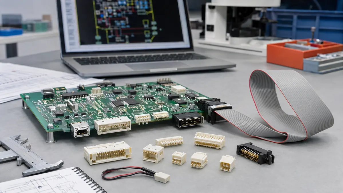
This guide is written for engineers and technical buyers preparing a connector RFQ. For the related product-family context, review LinkManu’s I/O connectors for external and panel interface projects, then use the sections below to define the internal interface before samples or tooling are discussed.
Define the Application Boundary First
Before choosing a connector family, document what the interface must survive inside the product. Internal I/O connectors may route board-to-board signals, cable-to-board harnesses, front-panel signals, storage interfaces, service modules, or mixed power and control lines. Each case creates a different tradeoff between density, retention, routing clearance, inspection access, and supply continuity.
A useful brief should answer where the connector sits, how often it will be mated, whether the line is sensitive to impedance or crosstalk, and whether the operator can see the latch during assembly. If these points are missing, purchasing can only compare part numbers and lead times. With them, a supplier can review the connector against the actual application instead of offering a loose substitute.
Engineering check: if the board, cable, and enclosure are already frozen, ask whether the connector choice still allows proper mating angle, cable bend space, latch access, and inspection. A small connector is not a good choice if production cannot assemble it repeatably.
Separate Electrical Needs from Datasheet Assumptions
Electrical review should cover current path, voltage environment, grounding, insulation needs, contact resistance stability, and signal behavior. Headline ratings are not final design approval. The selected connector still needs to be checked with the board stackup, cable route, enclosure temperature, and service life expected in the product.
For high-speed internal links, do not approve a connector only because the family name sounds suitable. The team should review the channel model, pad transition, shielding approach, grounding path, and validation plan. For lower-speed control or power signals, the bigger risk may be contact stability, wire termination quality, accidental unmating, or heat around dense pin groups.
Review Mechanical Fit Before Samples Are Ordered
Mechanical fit is where many internal connector selections fail late. Pitch, pin count, stack height, mating height, cable exit direction, keep-out zones, and board mounting style should be reviewed together. A connector can save board area and still create a problem if the cable bends directly into a housing wall or if the latch is hidden under another module.
The housing also needs attention. Material choice, molding stability, flame-retardant requirements, cleaning exposure, humidity, and heat should be stated as project requirements for supplier review. If the connector sits near a service panel or moving assembly, retention and polarization should be checked with real handling conditions rather than only a static drawing.
Compare Connector Families by Use Case
There is no single best internal I/O connector family. The right choice depends on the way the interface is used, the available space, the expected mating process, and the validation burden the project can support.
| Connector family | Where it usually fits | Selection risk to check |
|---|---|---|
| Board-to-board or mezzanine | Parallel boards, embedded compute modules, compact internal assemblies. | Alignment, mating height, insertion force, airflow clearance, and signal path validation. |
| Wire-to-board | Harnessed internal routing for sensors, fans, controls, or power paths. | Latch design, wire termination, strain relief, current path, and service handling. |
| Cable-to-board or ribbon interfaces | Front panels, serviceable subassemblies, modular boards, and legacy internal buses. | Cable bend radius, keyed mating, cable exit direction, and repeatable assembly. |
| High-speed internal links | Storage, compute expansion, and dense data paths. | Channel validation, grounding, shielding, pad transition, and PCB layout environment. |
For compact RF or coaxial interfaces, geometry can drive the decision as much as electrical intent. The related resource on SMA connector size for I/O connector design is a useful reminder that connector dimensions should be reviewed with the mating system and validation method, not treated as an isolated search term.
Ask the Supplier for a Validation Plan, Not Only a Quote
A practical supplier review should translate requirements into a sample and inspection plan. Ask how tooling, molding, contact forming, plating requirements, assembly, and final inspection will be controlled for this project. If the design needs a custom connector or modified housing, early design-for-manufacturing review can expose latch interference, cable strain, weak housing geometry, or shrinkage risk before tooling is released.
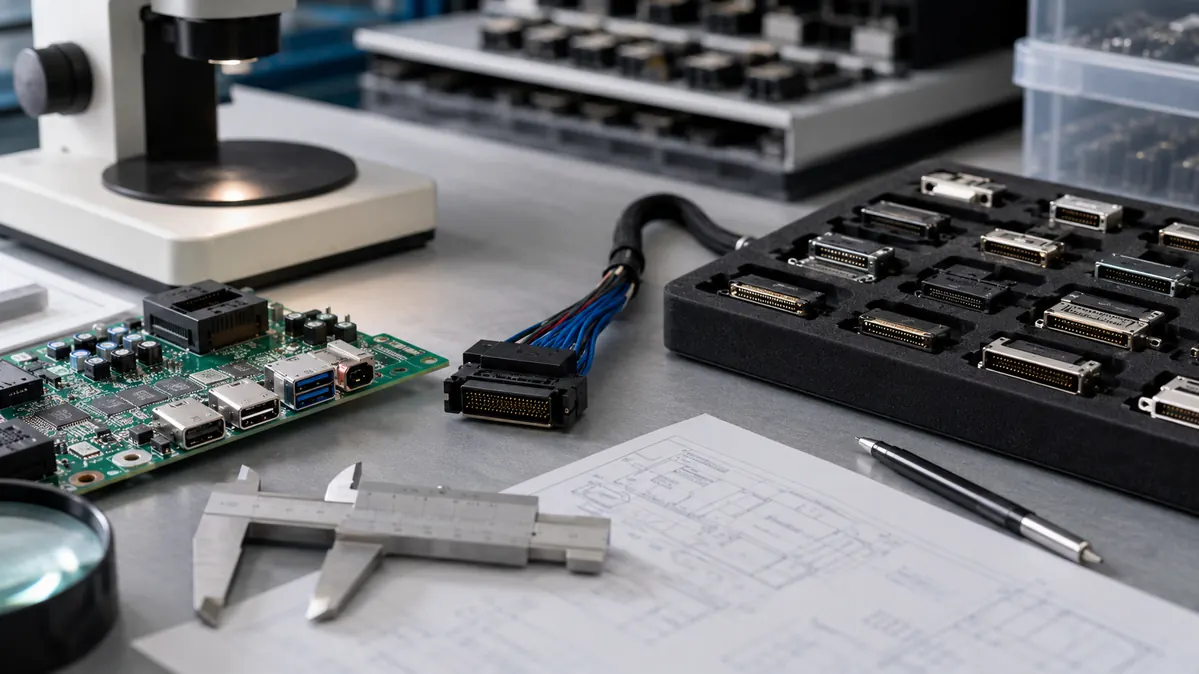
Validation should match the product risk. For some projects, mechanical fit, retention, assembly process review, and electrical continuity may be the main checks. For projects with high-speed signals or harsh handling, the team should also confirm the signal-path review, grounding method, environmental exposure, and any test documentation required by the customer drawing or end application.
Prepare an RFQ That Engineers Can Actually Review
A good RFQ removes guesswork. Include the drawing, BOM, connector location, board constraints, cable route, preferred mating direction, expected mating frequency, and any known environmental stress. If the project is still open, state which items are undecided so the supplier can recommend options without pretending every parameter is already fixed.
- Connector family, pitch, pin count, and mating height required by the design.
- Board, cable, enclosure, or panel constraints around the mating interface.
- Signal, power, grounding, and shielding requirements that need review.
- Expected service access, vibration, handling, and mating frequency.
- Housing material, flame-retardant, cleaning, or heat conditions to confirm.
- Sample validation expectations before production approval.
- Whether the project needs a compatible option, a modified connector, or a new design based on drawings.
Frequently Asked Questions
What matters most when selecting internal I/O connectors?
Check electrical behavior, mechanical fit, retention, housing conditions, assembly access, and supply continuity together. A connector can pass one area and still fail the project if another is ignored.
Should I choose the smallest internal I/O connector available?
No. Choose the smallest connector that still supports cable routing, latch access, inspection, signal review, and handling. Smaller parts can increase assembly sensitivity.
When should the supplier be involved?
Before the PCB and enclosure are frozen. Early review leaves time to adjust mounting, cable exit, latch access, and validation steps.
What should I send for an engineering review?
Send the drawing, BOM, target application, mating part details, board constraints, cable path, and any required test documentation. You can also contact engineering support when the stackup or sample information is ready.
Send Your Connector Requirement
Share your drawing, BOM, target application, and project constraints. LinkManu can review connector fit, sample options, documentation needs, and RFQ readiness before final selection.

Technical content reviewed by LinkManu Engineering Team
Prepared by LinkManu Editorial Team for B2B connector engineers, sourcing teams, and product development projects. Updated 2026.