
Cable Assembly Guide
How to Replace a Ribbon Cable Connector Safely
Learning how to replace a ribbon cable connector is not only a repair task. In industrial equipment, test instruments, control modules, and compact electronic devices, the connector also affects signal reliability, routing, strain relief, and future serviceability. A rushed replacement can bend pins, damage PCB pads, reverse pin orientation, or leave a weak termination that passes a quick bench check but fails later under vibration, handling, or thermal cycling.
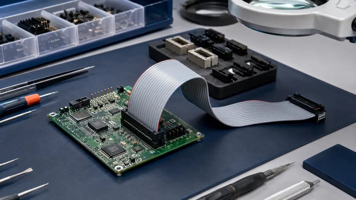
This guide explains the practical replacement sequence and the engineering decisions behind it: how to disconnect a ribbon cable without damage, how to remove a ribbon cable connector from a PCB when rework is required, how to evaluate whether the cable can be repaired, and when a complete custom cable assembly is the more reliable sourcing path.
Engineering note: The exact connector pitch, conductor count, plating, mating interface, and termination method should be confirmed from the equipment drawing, original BOM, or connector datasheet. Do not assume that a mechanically similar ribbon cable connector is electrically equivalent.
Why Ribbon Cable Connector Replacement Often Fails
Ribbon cable connectors look simple, which is why many failures begin with overconfidence. A technician may pull on the cable instead of the connector body, pry a ZIF lock with a metal tool, press an IDC connector unevenly, or desolder a board-mounted connector without protecting nearby pads. These mistakes can create intermittent opens, cracked solder joints, damaged insulation, or misaligned contacts.
The problem is that many of these defects are not visible during a basic inspection. A cable may pass continuity at room temperature but fail after movement. A partly lifted PCB pad may work during reassembly and then open under vibration. A reversed cable may fit the connector body while placing power, ground, or signal pins in the wrong locations.
Common failure patterns to watch for
- Pulling the ribbon cable instead of releasing the connector or latch.
- Closing a ZIF or FFC lock while the cable is not fully seated.
- Pressing an IDC connector without an even, controlled termination tool.
- Using a connector that fits physically but does not match the original pinout.
- Applying excess heat during PCB rework and weakening pads or nearby components.
- Reusing a cable that already shows cracked insulation, corrosion, or repeated flex damage.
Types of Ribbon Cable Connectors to Identify First
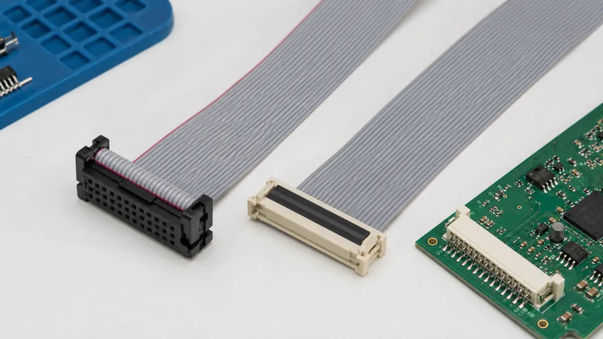
Before any replacement work begins, identify the connector family and termination style. IDC, ZIF/FFC, and soldered board connectors are handled differently, and each has a different risk profile during field service.
| Connector Type | How It Terminates | Replacement Considerations | Typical Review Use |
|---|---|---|---|
| IDC ribbon connector | Contacts pierce the insulation and make contact with the conductors when the connector is pressed onto the cable. | Requires even pressure and the correct termination tool. Uneven seating can create intermittent circuits. | Internal harnesses, board-to-board cable links, serviceable equipment, and assemblies where repeatable cable preparation matters. |
| ZIF or FFC connector | A flat flexible cable is inserted into a socket and secured by a hinged or sliding lock. | The lock and cable end are delicate. Bent stiffeners, contamination, or incomplete insertion can cause unreliable contact. | Compact electronics, displays, control panels, and designs where low insertion force and limited space are important. |
| Soldered board connector | The connector is soldered directly to PCB pads or through-holes. | PCB pad protection is the main risk. Rework should be done with controlled heat, flux, magnification, and suitable tools. | Applications where the connector is part of the board-level design and field replacement carries higher rework risk. |
Before Replacement: Confirm the Engineering Details
A reliable replacement starts with documentation, not tools. Confirm the original part number if available, then verify connector style, pin count, cable width, conductor orientation, mating header, latch direction, and routing path. If the original part number is unavailable, compare the assembly against drawings, photos, a known-good sample, or the equipment service documentation.
Selection factors that should be checked
- Pin 1 orientation: The colored edge of a ribbon cable can help identify orientation, but it must still match the drawing and the mating device.
- Pitch and conductor count: These should be confirmed from documentation or measured with appropriate inspection tools rather than guessed visually.
- Contact plating and mating interface: Mixed contact systems can create reliability risks if the original design requirements are not reviewed.
- Insulation and cable material: Flexibility, chemical exposure, temperature environment, and bend radius all influence whether a repaired cable is suitable.
- Strain relief and routing: The replacement should not transfer cable movement directly into the connector termination.
- Traceability needs: Industrial, automotive, and regulated products may require controlled parts, approved processes, and documented inspection records.
If the original assembly involves shielding, stiffeners, overmolding, combined power and signal conductors, or non-standard routing, a repair bench replacement may not be enough. In that case, it is better to review the part as a complete cable assembly through the appropriate product family and project documentation.
Step-by-Step: How to Replace a Ribbon Cable Connector
The steps below are written as an engineering workflow. They should be adapted to the specific connector design, PCB construction, and equipment documentation.
1. Power down and protect the assembly
- Disconnect all power sources and allow stored energy in the equipment to discharge according to the service procedure.
- Use ESD protection for the board, tools, and work surface.
- Photograph the existing routing path, connector direction, latch position, and strain relief points.
- Prepare the correct replacement connector, termination tool, inspection magnification, and continuity test equipment.
2. Disconnect the ribbon cable without damage
- For a ZIF or FFC connector, open the locking bar or slide lock gently before pulling the cable.
- For an IDC-style cable connection, pull on the connector body evenly rather than pulling on the ribbon cable.
- For latched connectors, release the latch fully before lifting the connector from the mating header.
- Inspect the cable end immediately after removal. Look for torn insulation, bent contacts, contamination, or crushed cable edges.
3. Remove the old PCB connector only when required
- If the connector is board-mounted, first confirm that the connector itself is faulty and not only the cable.
- Use controlled heat, suitable flux, and board protection during desoldering.
- Lift the connector straight up when solder is fully released. Avoid sideways force on pads or through-holes.
- Clean and inspect the pad area under magnification before installing a new connector.
4. Decide whether to repair the cable or replace the assembly
Minor end damage may sometimes be corrected by trimming and re-terminating the cable if there is enough service length and the conductor condition is still sound. However, a cable with cracked insulation, repeated flex damage, corrosion, heat exposure, or unknown service history should be treated carefully. A cosmetic repair does not restore conductor integrity, impedance control, strain relief, or documented traceability.
For production equipment or repeated field failures, a fully built replacement through custom cable assemblies and wire harnesses can reduce rework variability and make future maintenance easier to control.
5. Attach the new connector and verify alignment
- For IDC termination, align pin 1 and seat the cable squarely before pressing the connector with the proper fixture.
- For ZIF or FFC insertion, insert the cable evenly to the correct depth, confirm contact direction, then close the lock without forcing it.
- For soldered connectors, tack the connector in alignment before completing the solder joints.
- Inspect for uneven seating, solder bridges, cold joints, bent pins, and cable skew before power is restored.
6. Test before returning the equipment to service
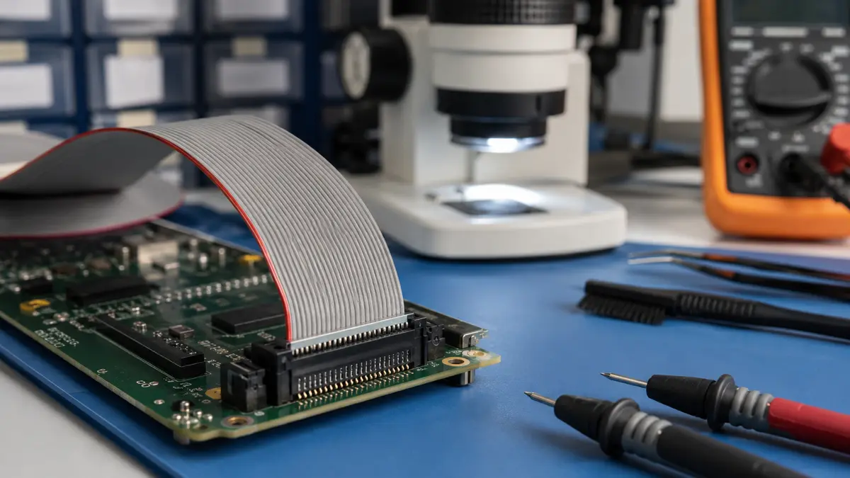
- Perform pin-to-pin continuity checks against the expected pinout.
- Check for unintended continuity between adjacent conductors or contacts.
- Run the equipment function that actually uses the signals carried by the ribbon cable.
- Record the replacement part, inspection result, and any deviations from the original assembly.
When a Complete Cable Assembly Is the Better Option
Knowing how to remove a ribbon cable connector is useful, but repeated connector-level repairs can point to a larger design or sourcing issue. If the same assembly fails again, the root cause may be routing strain, poor bend relief, environmental exposure, insufficient latch retention, or a connector choice that does not match the application.
A complete cable assembly review can evaluate the cable, connector, strain relief, shielding, routing, and test requirements together. LinkManu capability references include assembly, injection molding, stamping, and tooling, which can support projects that need more than a standard off-the-shelf connector. For non-standard mating interfaces or custom housings, custom connectors may also be reviewed as part of the design.
For buyers working with industrial or automotive programs, documentation also matters. Available quality and environmental references such as IATF 16949 and ISO 14001 should be reviewed during sourcing so the replacement path supports the project audit trail rather than creating an undocumented field workaround.
Procurement Checklist Before You Request a Replacement
- Photos of the existing connector from multiple angles.
- Current cable length, conductor count, and connector orientation.
- Original drawing, BOM, part number, or equipment model information if available.
- Application environment, including vibration, movement, moisture, chemicals, and service access.
- Whether the issue is a one-time repair, recurring field failure, or new production sourcing requirement.
- Expected inspection or documentation requirements for the finished assembly.
Practical takeaway: Treat a ribbon cable connector replacement as a controlled interconnect review. If the connector, cable, and routing are not checked together, the repair may only move the failure point to a later date.
Frequently Asked Questions
How do you replace a ribbon cable connector?
Identify the connector type, power down the equipment, release the existing connector without pulling on the cable, inspect the ribbon end and PCB, attach the new connector using the correct termination method, then verify orientation and continuity before powering the device again.
How do you disconnect a ribbon cable safely?
Release the latch or locking bar first, hold the connector body rather than the cable, and pull evenly in the intended direction. If the connector does not move easily, stop and confirm the locking mechanism before applying more force.
Can you repair a damaged ribbon cable?
It depends on the damage. Minor end damage may be re-terminated if the remaining cable is healthy and long enough, but cracked insulation, corrosion, repeated flex damage, or unknown internal conductor damage usually points toward replacing the complete assembly.
What connector details should be confirmed before ordering?
Confirm connector family, pitch, conductor count, pin 1 orientation, mating interface, cable length, contact requirements, routing, strain relief, and documentation needs. These details should come from drawings, datasheets, samples, or an engineering review.
Request a Ribbon Cable Assembly Review
Share your drawing, sample photos, BOM, or application notes so LinkManu can review connector selection, cable routing, strain relief, and production documentation requirements.

Technical content reviewed by LinkManu Engineering Team
Prepared by LinkManu Editorial Team for B2B connector engineers, sourcing teams, and product development projects. Updated 2026.